CREVIS Camera Manual

3CMOS Camera Manual

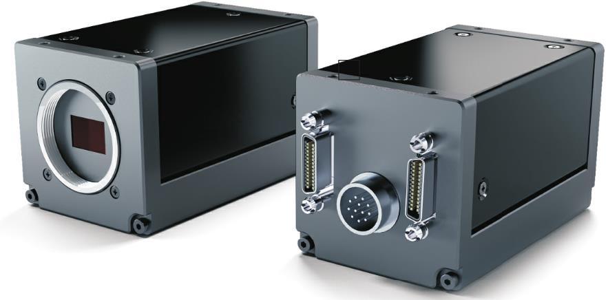
3 CMOS Sensor Color Camera

CameraLink Camera User Manual

TC-A160K-102

TC-A160K-102 3CMOS Camera

1. Preparation

1.1 Required Preparation Items

1.2 SDK

1.3 Precautions

  • Operating temperature: 0 deg C to +45 deg C
    Keep the ambient temperature stable because data output may vary according to temperature changes.
  • Leakage and humidity caution
    The product itself is not waterproof, so avoid exposing it to excessive humidity.
  • Magnetic and electric fields
    Because the I/O signals use low-voltage, low-current LVDS around 300 mV, strong magnetic or electric fields may distort the signals.
  • Ventilation
    Power consumption differs depending on the usage environment, but because power consumption is high, do not seal the area around the product or block airflow; maintain proper ventilation.
  • Initial operating condition
    When applying power to the product, apply power only after the cable is connected between the camera and the Frame Grabber.
  • Product performance may vary depending on cable characteristics.
  • To comply with CE standards, use a standard Camera Link cable or an equivalent high-shield cable. Recommended cable: 3M 14B26-SZLB-xxx-SKC.
  • This product may be changed without notice for functional and performance improvements.

2. Product Specifications

2.1 Product Overview

2.2 Main Specifications

Spec.TC-A160K-102Remark
SensorSony CMOS 1.6MIMX273
Sensor Format1/2.9″
Pixel Size (um)3.45 x 3.45
Active Pixels1456 x 1088
Frame Rate51 fps (@ Base RGB8) / 102 fps (@ Full RGB8)
Scanning SystemProgressive
Sync. SystemInternal (Freerun) or External (CC1~CC4 / Opto-isolated Input x1 / GPIO(TTL) x2 / Software)
Trigger ModeTimed, Trigger Width
Shutter Speed1us ~ 3sec (+14.26us)
GainAnalog (Master Gain + RGB Gain) : 0dB ~ 36dB (1x ~ 63.1x)
Black Level0~4095 (ADC 12bit)
GammaAdjustable LUT (12bit to 12bit)
Auto White BalanceOff / Once / Continuous
Auto Gain / ExposureOff / Once / Continuous
ROIVertical & Horizontal ROI Support
Video I/FCamera Link (SDR x1)
Video Format8bit RGB
CommunicationRS232 via CameraLink connector
C/L Pixel Freq.85 MHz
SNR35dB
Function ControlGainAuto, ExposureAuto, BalanceWhiteAuto,
Acquisition Frame Rate (Adjustable),
Defect Correction, Noise Reduction,
Shading Correction (FFC), Color Transformation Control
Lens mountC mount
Optical accuracyOptical center ≤ ± 0.15 mm
Power Supply12~24VDC ± 10% (DC IN)
Consumption< 4.5W
Weight< 163g
Dimension44 x 44 x 73.5 ㎜
Operating / Storage0℃ ~ +45℃ (with < 20~80% RH) / -20℃ ~ +60℃
Vibration / Shock98 m/s² (10.0 G) / 490 m/s² (50.0 G)
Standard CompliancyCE (EN61326-1; 2006; Class A)
EnvironmentsRoHS / WEEE

3. Camera Interface

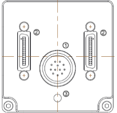
3.1 Back Panel

TC-A160K-102 back panel
NO.NameRemark
1Power & I/O Connector12Pin Circular
2CameraLink ConnectorSDR26
3LED indicatorLED

3.2 Camera DC IN / External I/O Pin Map

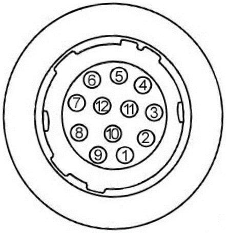
1) 12 pin Circular Connector

12 pin circular connector
No.NameIN/OUTDescriptionRemark
1GNDIN
2Power ININ10.8V ~ 26.4V Input Range
3---
4---
5Trigger1-INOpto-Isolated Trigger Input-Opto-Isolated Trigger Input+
(2.5V~24V)
6Trigger1+IN
7GPIO 0 (TTL)IN/OUTInput (3.3V~24V) / output (3.3Vp-p)
8GNDIN
9NC--
10GPIO 1 (TTL)IN/OUTInput (3.3V~24V) / output (3.3Vp-p)
11Power ININ10.8V ~ 26.4V Input Range
12GNDIN

3.3 CameraLink Connector Pin Map

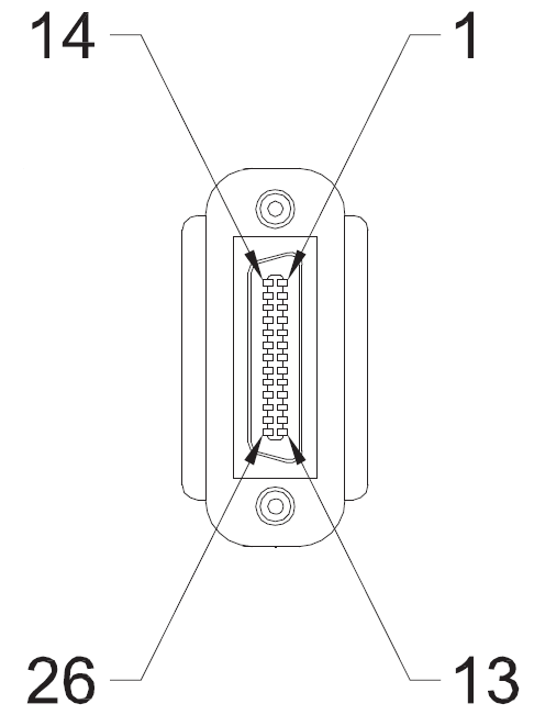
1) Mini CameraLink™ Connector1 - Base (SDR)

Mini CameraLink connector pin numbering
PIN NO.Signal NamePIN NO.Signal Name
1GND14GND
2X0-15X0+
3X1-16X1+
4X2-17X2+
5Xclk-18Xclk+
6X3-19X3+
7SerTC+20SerTC-
8SerTFG-21SerTFG+
9CC1-22CC1+
10CC2+23CC2-
11CC3-24CC3+
12CC4+25CC4-
13GND26GND

2) Mini CameraLink™ Connector2 - Medium/Full (SDR)

Mini CameraLink connector pin numbering
PIN NO.Signal NamePIN NO.Signal Name
1GND14GND
2Y0-15Y0+
3Y1-16Y1+
4Y2-17Y2+
5Yclk-18Yclk+
6Y3-19Y3+
7100ohm terminated20100ohm terminated
8Z0-21Z0+
9Z1-22Z1+
10Z2-23Z2+
11Zclk-24Zclk+
12Z3-25Z3+
13GND26GND

3.4 LED Status

LightStatus
OrangeCamera initialization.
GreenNormal operation.

3.5 External I/O Internal Circuit

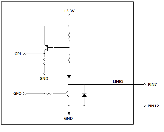
GPIO TTL internal circuit
1) GPIO(TTL)
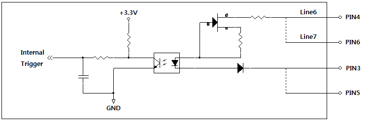
Opto-isolated input internal circuit
2) Opto-isolated Input

3.6 CameraLink Interface Timing

3.6.1 Data order of the CameraLink

CameraLink data order

3.6.2 Color RGB Order (8bit)

Color RGB order 8bit

4. Camera Functions

4.1 Image Format Control

4.1.1 Device Tap Geometry

This function sets Device Tap Geometry.

The Frame Grabber camfile must be changed according to the configured CameraLink Tap Geometry.

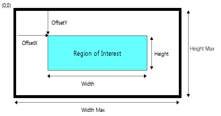
4.1.2 ROI

WidthMAX >= Offset X + Width
HeightMAX >= Offset Y + Height

By setting Width, Height, Offset X, and Offset Y, the user can receive only the desired area. The frame rate increases as the image size becomes smaller.

ROI region and offsets
ItemSetting ValueStep
ADC 8BitADC 10Bit, 12Bit
Width520 to 1456264 to 14568 pixels
Height4 to 10884 to 10884 pixels
OffsetX0 to 9360 to 11928 pixels
OffsetY0 to 10840 to 10842 pixels

4.1.3 Reverse X, Y

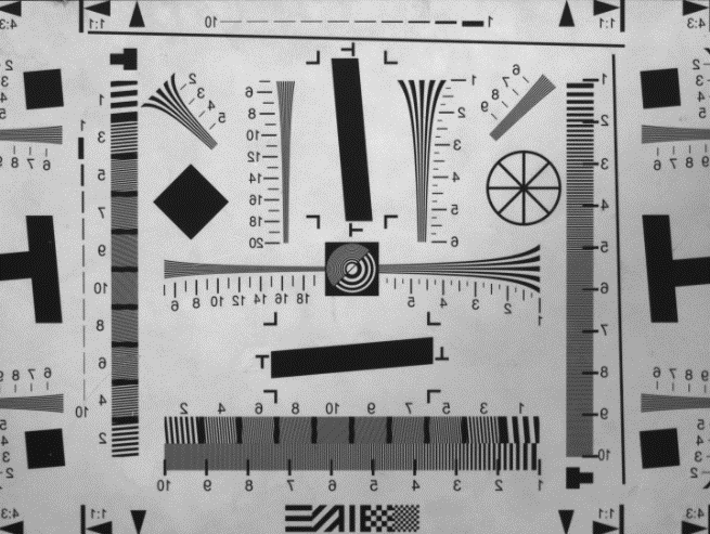
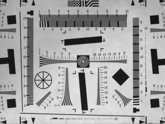
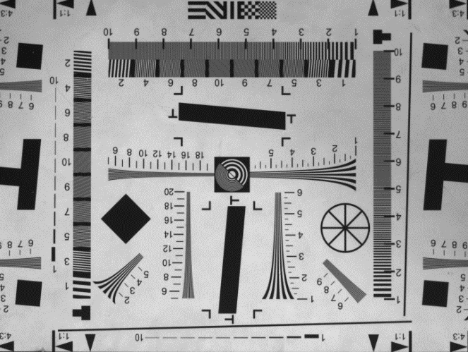
This function changes the left/right and top/bottom orientation of the image.

Original image
Original
Reverse X image
Reverse X
Reverse Y image
Reverse Y
Reverse X and Y image
Reverse X and Y

Figure 1 - Reverse Image

4.1.4 ADC Bit Depth

This function changes the bit depth of the image output from the sensor. It can be set to 8-bit, 10-bit, or 12-bit.

In 8-bit mode, the image is approximately four times brighter than in 10-bit or 12-bit mode.

4.1.5 Pixel Format

This function changes the image format output from the camera. Only 8-bit RGB mode is supported.

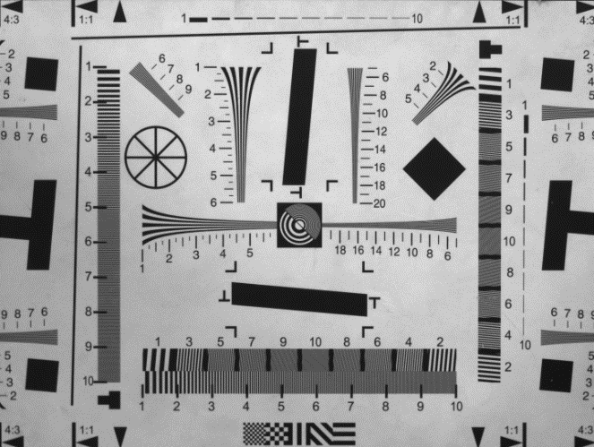
4.1.6 Test Pattern

Displays a test pattern image.

Grey Horizontal Ramp
Grey Vertical Ramp
Grey Vertical Ramp
Grey Horizontal Vertical Ramp

Figure 2 - Test Pattern Image

4.2 Acquisition Frame Rate Control

This function adjusts the Frame Rate.

ItemSetting ValueDescription
Acquisition Frame rate EnableOff, OnOff: operates at the maximum frame rate available with the current camera settings.
On: operates at the configured frame rate.
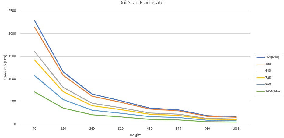
Acquisition Frame rate1 to 2180The maximum value differs depending on resolution. (See Table 1)
H \ W2644806407289601456
4022872141160514171074710
12011571084813717544539
240665622467412312207
320518485364321243161
480359336525223169112
54432030022519815099
9601871751311168858
10881661551171037852

Table 1 - Maximum Frame Rate (fps) by Resolution - based on ADC 12-bit

Frame rate by resolution
Figure 3 - Frame Rate Change by Resolution

4.3 Exposure Control

4.3.1 Exposure Mode

This function determines the exposure method.

ModeDescription
TimedExposes for the configured time value.
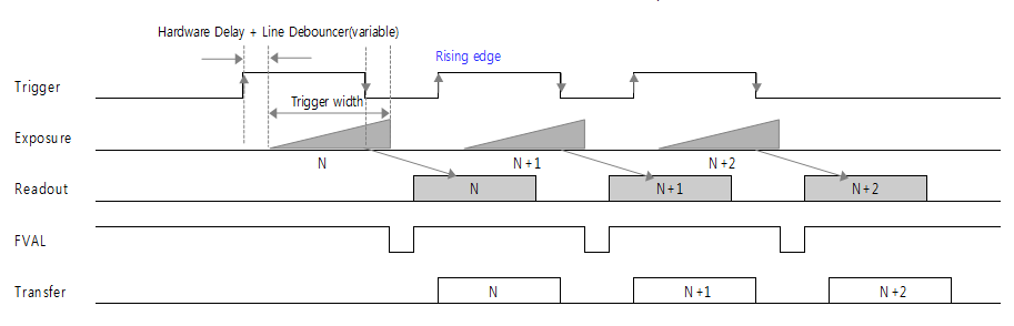
Trigger WidthExposes for the pulse width of the input trigger signal.
If Trigger Activation is Rising Edge, exposure lasts while the value is High; if Falling Edge, exposure lasts while the value is Low.

4.3.2 Exposure Time

Sets the exposure time. This applies only when the camera is set to Timed mode.

Note: actual exposure time = setting time + 14.26 us (when set to 1 us, exposure is 15.26 us)

Note: Exposure Start/End Delay: 3 HDs (52 us based on Base RGB8; varies depending on ROI and CL Configuration.)

Note: Delay from Exposure End to the start point of FVAL: (31 + ROI OffsetY) HD

4.3.3 Exposure Auto

This function automatically adjusts Exposure Time to maintain the brightness desired by the user. It can be set when ExposureMode is set to Timed.

ItemSetting ValueDescription
Exposure AutoOff
Once
Continuous
Off: sets Exposure Time manually.
Once: adjusts exposure time only once to change the image to the desired brightness value.
Continuous: continuously adjusts exposure time to maintain the desired brightness value.
Auto Exposure Target0 to 255Sets the desired brightness value (unit: DN) / based on 8-bit
Auto Exposure Time Lower Limit1 to 3,000,000usMinimum Exposure Time that can be set automatically
- AEMIN: 1 us unit
Auto Exposure Time Upper Limit1 to 3,000,000usMaximum Exposure Time that can be set automatically
- AEMAX: 1 us unit

* Exposure Time setting value may vary depending on Width/ADC bit settings.

4.4 Trigger Mode Control

Sets Trigger Mode.

ItemSetting ValueDescription
Trigger ModeOn, OffOff: the camera operates in Free Run mode. An internal trigger signal is generated. The trigger period is determined by Acquisition Frame Rate. If the Acquisition Frame Rate Enable function is Off, the camera operates at the maximum frame rate available with the current settings.
On: the camera operates in Trigger mode. Triggers are generated through hardware (Line 1 to 7) or software trigger.
Trigger SourceLine1, Line2, Line3,
Line4, Line5, Line6,
Line7, Software
Selects the source to be used as the trigger input. Refer to the Trigger Source section below for details.
Trigger Delay0x1 to 0xFFFFFFFF /
0 to 57,844,677
Adjusts Trigger Delay. TRGDLY
Refer to the Trigger Delay section below for details.
Line Debounce Time0x1 to 0xFFFFFFFF /
0 to 57,844,677
Adjusts Line Debounce Time. TRGFLTNUM
Refer to the Line Debounce section below for details.

4.4.1 Trigger Source

Defines the trigger source. This applies when Trigger Mode is On.

4.4.1.1 Hardware Trigger

1) CameraLink connector

2) 12-pin connector

4.4.1.2 Software Trigger

Generates a trigger through the software function.

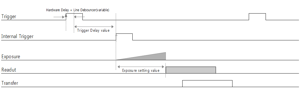
4.4.2 Trigger Delay

This function delays operation by the delay time set by the user after trigger input.

Trigger Mode : On
Trigger Delay : Delay Value
Exposure Mode : Timed

Trigger delay timing

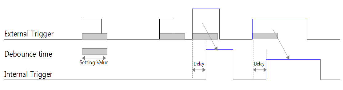
4.4.3 Line Debounce

This function removes chattering noise from trigger signals that pass through external I/O. It operates only for signals maintained longer than the configured time.

Line debounce timing

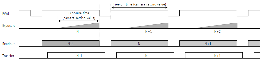
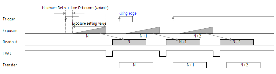
4.4.4 Timing by Exposure Mode

Freerun mode timing
1) Freerun mode Timing
Trigger timed mode timing
2) Trigger Timed mode Timing
Trigger width mode timing
3) Trigger Width mode Timing
4) Hardware Delay
RisingFalling
GPIO(TTL)900 ns130 ns
Opto-isolated Input4.5 us80 us

4.5 Digital I/O Control

This function configures external I/O signals.

ItemSetting ValueDescription
Line SelectorLine1, Line2, Line3,
Line4, Line5, Line6,
Line7, Software
Selects the channel to configure.
Line ModeInput, OutputSelects either input or output.
Only Line5 can be set as output.
Line Inverter0, 1When enabled, the input signal is inverted.
Line Status0, 1Returns the current status of the selected line.
Line SourceOff,
Timer1 Active,
Exposure Active,
UserOutput1,
UserOutput2,
UserOutput3
Available only when configured as Output.
Off: not used.
ExposureActive: active during exposure time.
UserOutput1 to 3: maintains the user-configured output value independently of Input.
User Output SelectorUserOutput1
UserOutput2
UserOutput3
Selects the stored value to use.
User Output Value0, 1Sets the value selected by UserOutputSelector.

4.6 Counter and Timer Control

This function configures the strobe signal.

ItemSetting ValueDescription
Timer SelectorExposure
External Trigger
Internal VD
Exposure Active: generates a waveform from the exposure start point.
External Trigger: generates a waveform from the external trigger input point.
Internal VD: generates a waveform from the internal VD start point.
Timer Duration0x1 to 0xFFFFFFFFSets the High time of the strobe signal.
FLASHTIME
Timer Delay0x1 to 0xFFFFFFFFSets the Delay time of the strobe signal.
FLASHDELAY
Counter Event SourceExternalTriggerStart
ExposureStart
ExposureEnd
FrameEnd
ExposureStartMissed
ExposureStopMissed
This function checks camera operation reliability for externally input trigger signals.
ExternalTriggerStart: Count value increases by the number of external input triggers.
ExposureStart: Count value increases by the number of exposure starts.
ExposureEnd: Count value increases by the number of exposure ends.
FrameEnd: Count value increases by the number of FVAL signals received from the sensor.
ExposureStartMissed: Count value increases by the number of abnormal exposure starts.
ExposureStopMissed: Count value increases by the number of abnormal exposure ends.
Counter Value0 to 4,294,967,295Displays the Count value of EventSource.
The value is initialized at AcquisitionStart.

1) Timer Duration

2) Timer Delay

4.7 Gain Control

This function adjusts Gain.

ItemSetting ValueDescription
Gain SelectorAllSelects the Gain to configure. Only All can be selected.
Color Gain + All Gain = max. 36 dB
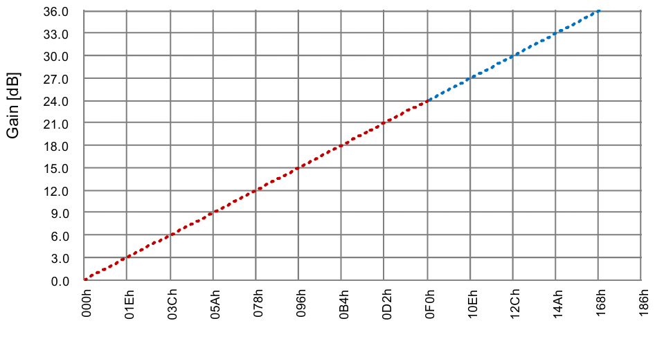
Gain Raw00 to 360Applies the desired Gain value numerically. (0 dB to 36 dB)
Amplifies the image signal to obtain a brighter image. Noise may also increase.
Applied as shown in the Gain Curve of Figure 3.
Gain Abs1 to 6308Applies the desired Gain value as a multiplier. (x1 to x63.08)
Applied the same as Raw.
Gain AutoOff, Once, ContinuousConfigures the AGC (Automatic Gain Control) function.
Off: sets Gain manually.
Once: adjusts the Gain value only once to change the image to the desired brightness value.
Continuous: continuously adjusts the Gain value to maintain the desired brightness value.

When Gain Auto is used together with AutoExposure, the priority is as follows.

  1. When the image becomes brighter: Exposure control is applied first, then Gain is set.
  2. When the image becomes darker: Gain Control is applied first, then Exposure is set.
Analog gain curve
Figure 3 - Gain Curve

※ Analog gain [dB] = Register setting value / 10

4.8 Black Level Control

This function adjusts the DC Offset of the image signal.

ItemSetting ValueDescription
Black Level SelectorAllSelects the Black Level to configure. Only All can be selected.
Black Level Raw0 to 4095Controls the analog Black Level. It can adjust the DC Offset of the image signal.

4.9 Balance Ratio Control

This function matches color gain.

ItemSetting ValueDescription
Balance Ratio SelectorRed, Green, BlueSelects the color whose color gain will be adjusted.
Balance Ratio0 to 4095Adjusts the gain value for the selected color.
Balance White AutoOff, Once, ContinuousOnce: adjusts color gain only once to set White Balance.
Continuous: continuously adjusts color gain to maintain White Balance.

* When using Balance White Auto, better results can be obtained under a subject condition with uniform brightness, such as white paper.

4.10 User Set Control

This function saves or loads values configured by the user.

ItemSetting ValueDescription
User Set SelectorDefault
Userset1
Userset2
Userset3
Default: factory-stored camera settings. They cannot be saved and can only be loaded.
Userset1/2/3: user-defined save/load is available. Saved settings are retained after power On/Off.
User Set LoadExecuteLoads the setting selected by Usersetselector.
User Set SaveExecuteSaves settings to the selected Usersetselector item.

4.11 LUT Control

The LUT function nonlinearly adjusts the image signal.

ItemSetting ValueDescription
LUT SelectorRed, Green, BlueSelects the color to configure.
LUT Position SelectorPosition 0 to Position 11Selects the position to configure.
One of 12 divided areas can be selected.
LUT Position X0 to 4095Adjusts the setting value.
LUT Position Y0 to 4095Adjusts the setting value.

Ex)

Index01234567891011
X020474095000000000
Y040954095000000000
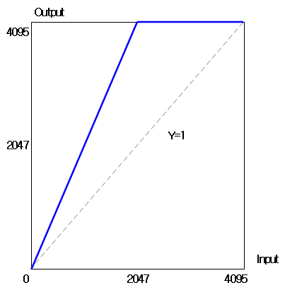
LUT gamma curve example

In the example Gamma curve calculation, values entered up to Index 2 participate in the curve calculation (X=4095), and the blue curve in the figure is entered into the LUT.

4.12 Gamma Control

This function adjusts Gamma.

ItemSetting ValueDescription
Gamma EnableRed, Green, BlueEnables the Gamma value of the configured color.
Gamma0 to 4.0Adjusts the Gamma value.

4.13 Defect Pixel Correction

This function corrects Defect Pixels.

ItemSetting ValueDescription
Defect SelectorRed, Green, BlueSelects the color to adjust.
Defect Filter EnableOn, OffSelects whether the adjusted value is enabled.
Defect Filter TestMode SelectorOff, Mark Black,
Mark White,
Mark white with black Background
Mark Black: displays the corrected position in black.
Mark White: displays the corrected position brightly.
Mark white with black Background: displays the corrected position brightly on a black background.
Defect Pixel Replacement Count1 to 256Specifies the maximum number of Defect Pixels to correct.
Defect Pixel Index0 to 255Selects the Defect Pixel Index to correct.
Defect Pixel X Coordinate0 to 727Enters the X-axis coordinate value of the Pixel to correct.
Defect Pixel Y Coordinate0 to 539Enters the Y-axis coordinate value of the Pixel to correct.
Defect Pixel X Replace ExecuteExecuteSorts and applies the entered correction values.

4.14 Flat Field Correction

This function uniformly corrects the brightness values of the captured image.

ItemSetting ValueDescription
FFC EnableOn, OffSelects whether the corrected value is enabled.
Black CalibrationExecuteCorrects FPN using a dark image.
White CalibrationExecuteCorrects PRNU using a bright image.
FFC Save Load Flash Select0 to 3Selects the area where FFC data is read and stored.
FFC SaveExecuteSaves FFC data to the selected area.
FFC LoadExecuteLoads FFC data from the selected area.

4.15 Color Transformation Control

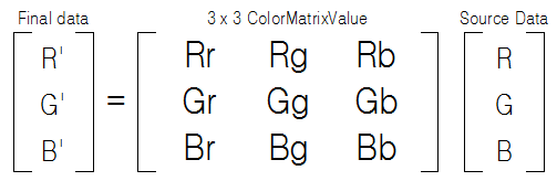
This function transforms colors using the input RGB colors through a user-configured 3x3 matrix ColorMatrixTable. (See Figure 4)

ItemSetting ValueDescription
Color Transformation Enable0, 1Enables Color Transformation.
Color Transformation Value SelectorGain00 to Gain22Refer to the Color Transformation Value Selector item below.
Color Transformation Value-8 to 8Adjusts the selected ColorMatrix value. (unit: ratio)
Color Transformation Offset SelectorOffset0
Offset1
Offset2
Offset0 : Red Color Offset
Offset1 : Green Color Offset
Offset2 : Blue Color Offset
Color Transformation Offset Value-255 to 255Adjusts the Offset value of the selected ColorMatrix.
Color Transformation Gain SelectorGain0
Gain1
Gain2
Gain0 : Red Color Gain
Gain1 : Green Color Gain
Gain2 : Blue Color Gain
Color Transformation Gain Value-8 to 8Adjusts the Gain value of the selected ColorMatrix. (unit: ratio)

Color Transformation Value Selector

3x3 color matrix table
Figure 4 - 3x3 Color Matrix Table

4.16 Noise Reduction

This function reduces image noise through a noise filter. When used, image edges may be damaged.

ItemSetting ValueDescription
Noise Reduction Enable0, 1Enables the Noise Reduction function.

5. Camera Appearance

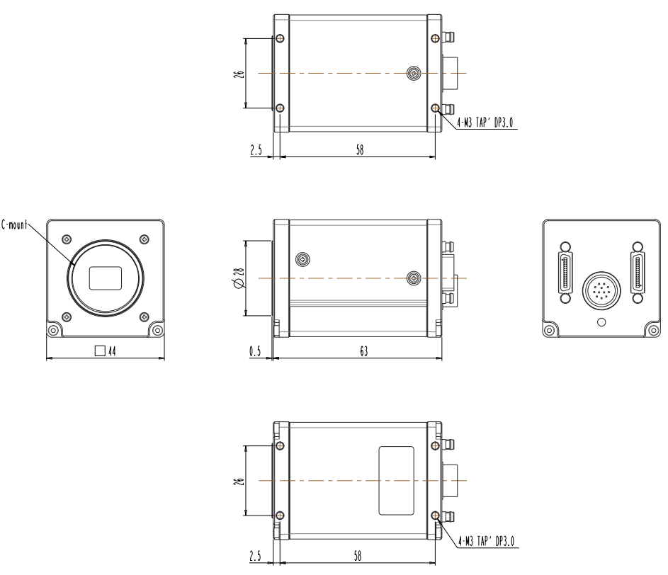
TC-A160K-102 dimensions

6. UART Communication

6.1 Communication Setting

ItemSetting Value
Baud RateDefault 9,600bps
Data Bit8bit
ParityNone
Stop Bit1bit
Flow ControlNone

6.2 Communication Format

W or Rnote1 Command Space Valuenote2 enter

6.3 Register Area

AreaAccess
ReadWrite
Factory AreaOX (Only factory write)
User 1 AreaOO
User 2 AreaOO
User 3 AreaOO

6.3.1 Register SAVE

CommandIndexDescription
SAVE1 ~ 3User Area Register Save

6.3.2 Register LOAD

CommandIndexDescription
LOAD0Factory Area Register Load
LOAD1 ~ 3User Area Register Load

6.4 Register List

Refer to CamGuide_CL software and Appendix A.

Appendix A. UART Command List

GroupR/WCommandParam 1Param 2Param 3Description
System
Control
SAVE0:Factory, 1~3:UserSave to EEPROM
LOAD0:Factory, 1~3:UserLoad from EEPROM
R/WUID0:Factory, 1~3:UserUser ID
RSNStringRead Serial Number
BAUDRATE0x2580 : 9600baud
0x4B00 : 19200baud
0x9600 : 38400baud
0xE100 : 57600baud
0x1C200 : 115200baud
Baudrate Write
EEPIDX0:Factory, 1~3 : UserRead Selected EEPROM Index
MODELStringRead Camera Model Name
VERStringFirmware Version
RXMLFILEStringRead XML File Version
RTEMP[15:0]DataRead Temperature Value
REBOOTCamera Device Reboot
Acquisition
Control
R/WFREERUN[31:0]DataRun-Free Time(unit:us)
R/WSHTSET[31:0]DataShutter(unit:us)
R/WFREERUNEN0:Disable, 1:EnableFreerun time User Control Enable
RMINFREERUN[31:0]DataRead Max Freerun Time(unit:us)
RMINSHTSET[31:0]DataRead Max Exposure Time(unit:us)
REALFREERUN[31:0]DataReal Freerun time(unit:us)
R/WAEMAX[31:0]DataAuto Exposure Max Time(unit:us)
R/WAEMIN[31:0]DataAuto Exposure Min Time(unit:us)
R/WAECMODE0:OFF, 1:Once, 2:ContinuesAuto Exposure Control Mode
R/WAETARGET0 ~ 255Auto Exposure Target Value
R/WTRGMODE0:Disable, 1:EnableTrigger Mode Enable
R/WEXPMODE0:Timed, 1:PluseWidthControlExposure Mode
R/WTRGSRC0:CC1, 1:CC2, 2:CC3, 3:CC4,
4:TTL(In or Out),
5:PhotoCoupler Input,
6:PhotoCoupler Output,
7:Software Trigger
Select Trigger Source Pin
R/WTRGDLY[31:0]DataTrigger Delay(unit:us)
R/WTRGFLTNUM[31:0]DataTrigger Filter Number(unit:us)
R/WSWTRIG1SW Trigger event assert when ‘1’
R/WFREERUN[31:0]DataRun-Free Time(unit:us)
WSHTSET[31:0]DataShutter(unit:us)
Image Format
Control
R/WTAPCFG1:1Tap, 2:2TapNum of CL Output Tap
R/WPIXFMT0x02180014 : RGB8
0x02300018 : RGB10
0x0230001A : RGB12
PixelFormat Select
R/WADCBIT8:8bit, 10:10bit, 12:12bitSensor AD conversion bits setting
RPIXCLK[31:0]DataRead PixelClock(unit:Hz)
RSTMCLK[31:0]DataRead StreamClock(unit:Hz)
RHMAX[31:0]DataRead 1HD Size(unit:clock)
R/WISCOLOR0:Disable, 1:EnableColor Mode Enable
R/WOUTSEL00:OFF, 1:Horizontal, 2:Vertical,
3:Horizontal + Vertical
Select TestPattern
R/WFLIPMODE0:narmal, 1:y, 2:x, 3:x & yFlip Mode Select
R/WBEN0x11:Disable
0x21:BinningVertical
0x22:BinningHorizontalVertical
Binning Mode Enable
R/WSKIP0x11:Disable
0x12:DecimationHorizontal
0x21:DecimationVertical
0x22:DecimationHorizontalVertical
Decimation Mode Enable
R/WWIDTHADC 8Bit : 520 ~ Width Max
ADC 10Bit : 264 ~ Width Max
ADC 12Bit : 264 ~ Width Max
Image Width Size Control(unit:pixel)
R/WHEIGHT4 ~ HeightMaxImage Height Size Control(unit:pixel)
ROFFSETXADC 8Bit : 0 ~ (WidthMax - 520)
ADC 10Bit : 0 ~ (WidthMax - 264)
ADC 12Bit : 0 ~ (WidthMax - 264)
Image OffsetX Control(unit:pixel)
ROFFSETY0 ~ (HeightMax-4)Image OffsetY Control(unit:pixel)
FFC
Control
R/WFFCEN0:Disable, 1:EnableFlatFieldCorrection Enable
WFFCSAVEFlatFieldCorrection Data Save
WFFCLOADFlatFieldCorrection Data Load
WBLACKCALFlatFieldCorrection:FPN Correction
WWHITECALFlatFieldCorrection:PRNU Correction
LUT
Control
R/WLUTEN0:Disable, 1:EnableLookUpTable Enable
R/WLUTSEL1:Red, 2:Green, 3:BlueLookUpTable Select
R/WLUTDATAPosition Index(0 ~ 11)XYLookUpTable Data(12bit to 12bit)
R/WGAMMAEN0:Disable, 1:EnableGamma Enable
R/WGAMMAGamma Data * 65536Gamma Data
Defect Pixel
Correction
R/WDEFCOREN0:Disable, 1:EnablePixelDefectCorrection Enable
R/WDEFCORSEL1:Red, 2:Green, 3:BlueDefectCorrection Select
R/WDEFHIGHLIGHT0:Normal, 1:Mark Black, 2:Mark White,
3:Mark White with Black Background
DefectCorrection Test Mode Select
R/WDEFCNT1-256DefectCorrection WriteCount
WIMMDEFCORImmediate Defect correction execution
WDEFEXECImmediate Defect correction execution
Trigger
Control
R/WFLASHSRC0:Exposure Start
1:Trigger Start
2:Internal VD (Freerun Start)
Flash Time Reset Signal Select
R/WFLASHDELAY[31:0]DataFlash Delay(unit:us)
R/WFLASHTIME[31:0]DataTrigger Time(unit:us)
RTRGSTARTCNT[31:0]DataRead External Trig Count
(Reset:Acq. Enable Start)
REXPSTARTCNT[31:0]DataRead Exposure Start Count
(Reset:Acq. Enable Start)
REXPENDCNT[31:0]DataRead Exposure End Count
(Reset:Acq. Enable Start)
FRAMEENDCNT[31:0]DataRead Sensor FVAL Rx Count
(Reset:Acq. Enable Start)
REXPSTARTMISSCNT[31:0]DataRead Exposure Start Error Count
(Reset:Acq. Enable Start)
REXPENDMISSCNT[31:0]DataRead Exposure End Error Count
(Reset:Acq. Enable Start)
Digital I/O
Control
R/WLINEMODE0:CC1, 1:CC2, 2:CC3, 3:CC4,
4:TTL(In or Out), 5:PhotoCoupler Input,
6:PhotoCoupler Output, 7:Software Trigger
0:Input,
1:Output
Line Mode Select
R/WLINEINVEN0:CC1, 1:CC2, 2:CC3, 3:CC4,
4:TTL(In or Out), 5:PhotoCoupler Input,
6:PhotoCoupler Output
0:Disable,
1:Enable
Line Inverter Enable
R/WLINESRC4:TTL(Out), 6:PhotoCoupler Output0:TimerActive,
1:ExposureActive,
2:Useroutput[0],
3:Useroutput[1],
4:Useroutput[2]
Line Source Select
RLINESTATUSbit[x]:Line NumberRead GPIO Status
R/WUSEROUTPUT0:User1, 1:User2, 2:User30:Disable,
1:Enable
GPO UserOutput Value
Analog
Control
R/WGAIN0~360Master Sensor Gain(unit:0.1db)
R/WGAINABS1~6309Master Sensor Gain(unit:0.01ratio)
R/WUCLAMP0:All, 1:Red, 2:Green, 3:Blue0~4095Sensor Blacklevel
RGAINMIN0~360Read Master Sensor Gain Min
RGAINMAX0~360Read Master Sensor Gain Max
RRGBGAINMAX0~360Read RGB(Red, Green, Blue) Gain Max Value
R/WAGCMODE0:OFF, 1:Once, 2:ContinuesAuto Gain Control Mode
R/WAWBMODE0:OFF, 1:Once, 2:ContinuesAuto White Balance Mode
R/WRGAIN0 ~ 360Red Gain(unit:0.1db)
R/WRGAINABS1~6309Red Gain(unit:0.01ratio)
R/WGGAIN0 ~ 360Green Gain(unit:0.1db)
R/WGGAINABS1~6309Green Gain(unit:0.01ratio)
R/WBGAIN0 ~ 360Blue Gain(unit:0.1db)
R/WBGAINABS1~6309Blue Gain(unit:0.01ratio)
R/WNREN0:Disable, 1:EnableHybrid Filter Enable
Color Transformation
Control
R/WCOLORMAT0:K00, 1:K01, 2:K02, 3:K10, 4:K11,
5:K12, 6:K20, 7:K21, 8:K22
DataFormat (2's complement)
[17]sign, [16:14]:integer,
[13:0]:fractional
Color Matrix Value * Color Matrix Factor
R K00, K01, K02
G K10, K11, K12
B K20, K21, K22
R/WMATROFFSETData Format (2's complement)
[8]sign, [7:0]integer
Red Matrix Offset
R/WMATGOFFSETData Format (2's complement)
[8]sign, [7:0]integer
Green Matrix Offset
R/WMATBOFFSETData Format (2's complement)
[8]sign, [7:0]integer
Blue Matrix Offset
R/WMATRGAINData Format (2's complement)
[17]sign, [16:14]:integer, [13:0]:fractional
Red Matrix Gain
R/WMATGGAINData Format (2's complement)
[17]sign, [16:14]:integer, [13:0]:fractional
Green Matrix Gain
R/WMATBGAINData Format (2's complement)
[17]sign, [16:14]:integer, [13:0]:fractional
Blue Matrix Gain
R/WMATEN0:Disable, 1:EnableColor Matrix Enable
ChunkR/WSCALEEN0:Disable, 1:EnableImage Scaling Enable
R/WSCALE[3:0]ScalingHorizontal,
[7:4]ScalingVertical
1:Off, 2:1/2 Scaling, 4:1/4 Scaling
Image Scaling Mode
R/WPROJEN0:Disable, 1:EnableProjection Enable (Edge Detection)
R/WPROJOBJTH0~100Image Object Threshold(unit:%)
R/WPROJDARKTH0~255Image Background Threshold

Appendix B. ACK Message

MessageDescription
“>OK”The command ran successfully.
"MSG_ERROR”An error occurred while executing the command.
"MSG_CMD_NOT_EXIST”Command does not exist.
"MSG_PARAM1_ERROR”Parameter 1 is invalid.
"MSG_PARAM2_ERROR”Parameter 2 is invalid.
"MSG_PARAM3_ERROR”Parameter 3 is invalid.
"MSG_PARAM4_ERROR”Parameter 4 is invalid.
"MSG_PARAM5_ERROR”Parameter 5 is invalid.
"MSG_PARAM6_ERROR”Parameter 6 is invalid.
"MSG_PARAM7_ERROR”Parameter 7 is invalid.
"MSG_DEVICE_ERROR”An error has occurred on the device.
"MSG_DEVICE_TIMEOUT”The device is response timed out.
"MSG_ACCESS_DENIED”Access is denied.
"MSG_NOT_SUPPORTED”Not supported.

Appendix C. Preparation for Camera Operation

1. SDK Installation

2. Camera Communication Connection Method

2.1 Run CamGuideCL

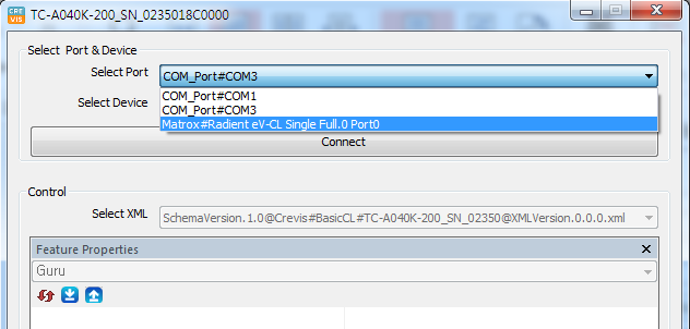
2.2 Select Port: select the port connected to the camera

CamGuideCL select port

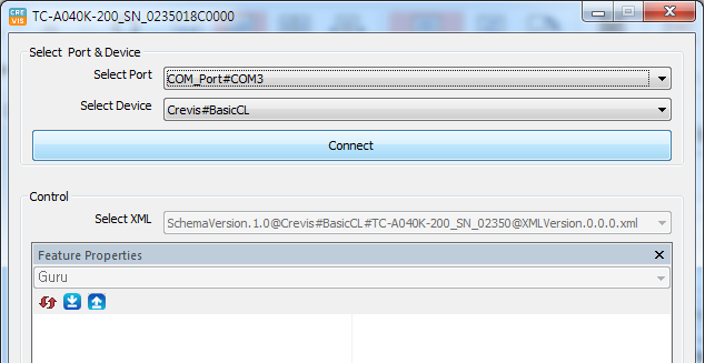
2.3 Click Connect

CamGuideCL connect

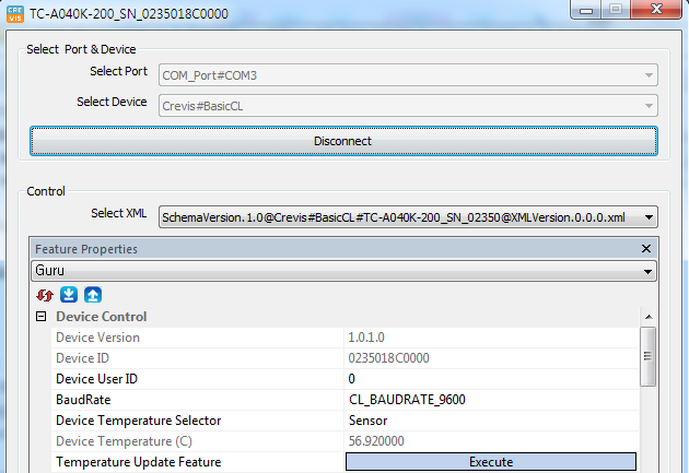
2.4 Connection Complete

CamGuideCL connected

* For detailed instructions, refer to the CamGuideCL manual.

Revision History

RevisionDateChangesRemark
1.02019.12Issued

Contact

Product Inquiry (Sales)

Tel : +82-31-899-4503
+82-31-899-4504
+82-31-899-4507

Fax : +82-31-899-4509

sh_lee@crevis.co.kr
dkahn@crevis.co.kr
mysung@crevis.co.kr

Technical Support

Tel : +82-31-899-4567

tjmoon@crevis.co.kr

Head Office

29-4, Gigok-ro, Giheung-gu, Yongin-si, Gyeonggi-do, Korea

www.crevis.co.kr