Operating temperature: 0 deg C to +45 deg C Keep the ambient temperature stable because data output may vary according to temperature changes.
Leakage and humidity caution The product itself is not waterproof, so avoid exposing it to excessive humidity.
Magnetic and electric fields Because the I/O signals use low-voltage, low-current LVDS around 300 mV, strong magnetic or electric fields may distort the signals.
Ventilation Do not seal the area around the product or block airflow; maintain proper ventilation.
Initial operating condition Apply power only after the cable is connected between the camera and the Frame Grabber.
Product performance may vary depending on cable characteristics.
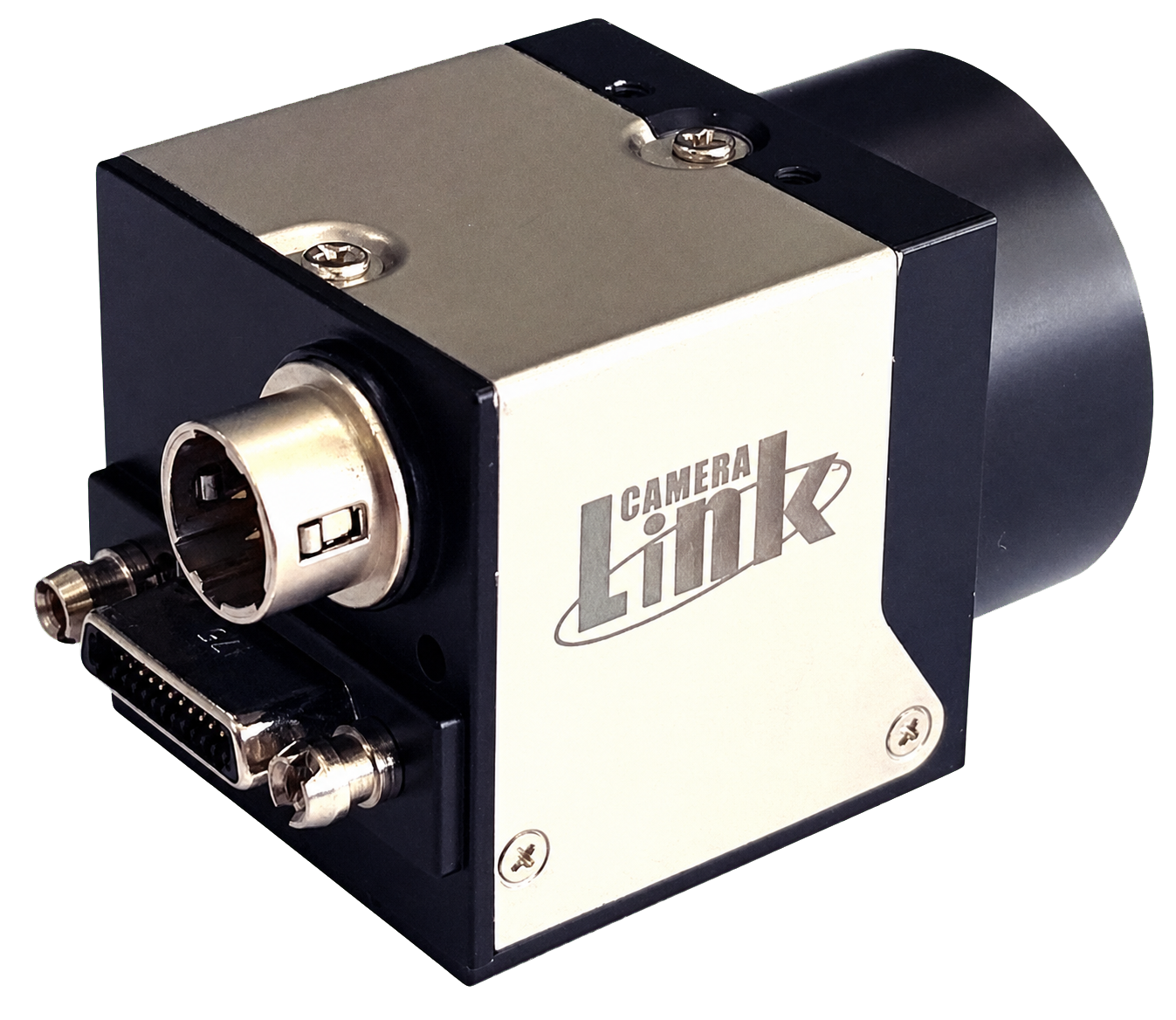
To comply with CE standards, use a standard Camera Link cable or an equivalent high-shield cable. Recommended cable: 3M 14B26-SZLB-xxx-SKC.
Specifications and performance may be changed without notice for product improvement.
2. Product Specifications
2.1 Product Overview
Sony CMOS Sensor Camera
ROI Scan support
Freerun and Trigger Mode support
CameraLink Interface
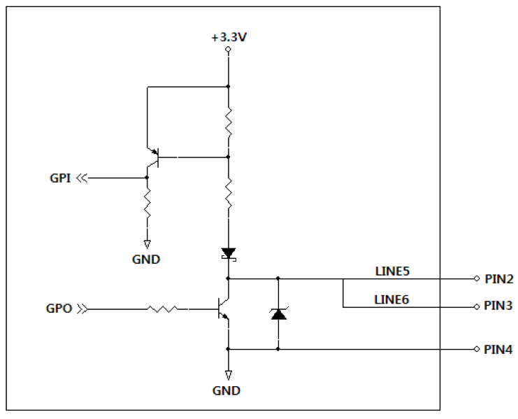
External General Purpose I/O (TTL) 2ch support
Power supply : DC 24V (10.8 ~ 26.4V range supported)
2.2 Main Specifications
Spec.
MC-A040M/K-523
MC-A160M/K-154
MC-A320M/K-55
MC-A500M/K-35 (MC-A500M-LF)
MC-A121M/K-20
MC-A121R/L-20
Sensor
0.4M IMX287LL(Q)R-C
1.6M IMX273LL(Q)R-C
3.2M IMX265LL(Q)R-C
5M IMX264LL(Q)R-C
12.2M IMX304LL(Q)R-C
12.1M IMX226CL(Q)J-C
Sensor Size
1/2.9″
1/2.9″
1/1.8″
2/3″
1.1″
1/1.7″
Pixel Size (µm)
6.90 × 6.90
3.45 × 3.45
3.45 × 3.45
3.45 × 3.45
3.45 × 3.45
1.85 × 1.85
Resolution (3Tap)
720 × 540
1440 × 1080
2048 × 1536 (2040 × 1536)
2448 × 2048
4096 × 3000 (4080 × 3000)
4016 × 3036 (4008 × 3036)
C/L Pixel Freq.
85MHz
85MHz
85MHz
85MHz (60MHz)
85MHz
85MHz
C/L Tap
3Tap / 2Tap / 1Tap
Frame Rate (Max)*
523.5fps
154.6fps
55.7fps
35.7fps (35.0fps)
20.3fps
20.0fps
Scanning Method
Full / ROI / Reverse (X,Y,ALL)
Full / ROI / Reverse Decimation (H+V) Binning (H+V, Mono only)
Full / ROI / Reverse Decimation (H+V)
Full / ROI / Reverse Decimation (H+V)
Full / ROI / Reverse Decimation (H+V)
Full / ROI / Reverse (X,Y,ALL)
Synchronization
Internal(Freerun), External(CC1~4 or Circular), Software trigger via PC
Trigger Mode
Timed, Trigger Width
GPIO
Transistor-Transistor-Logic(TTL) Input/Output 2ch
Shutter
Global Shutter
Rolling Shutter / Global Reset
Shutter Speed (Exposure Offset)
1µs ~ 3sec (14.26µs)
1µs ~ 3sec (13.73µs)
1µs ~ 3sec (13.73µs)
1µs ~ 3sec (13.73µs)
1µs ~ 3sec (14.26µs)
213.13µs ~ 3sec
Gain Abs
Analog : 0dB ~ 24dB (1× ~ 15.8×) Digital : 0dB ~ 18dB (1× ~ 8×)
Mono Model : Mono8/10 Color Model : Mono8/10, BayerRG8/10, BayerGB8/10, BayerGR8/10, BayerBG8/10, RGB8
SNR
B/W 37dB Color 40dB
B/W 31dB Color 35dB
B/W 36dB Color 40dB
B/W 37dB Color 41dB
B/W 39dB Color 40dB
B/W 38dB Color 41dB
Function Control
BalanceWhiteAuto < Off / Once / Continuous (Only Color Models) > GainAuto, ExposureAuto < Off / Once / Continuous > Acquisition Frame Rate(Adjustable), Shading Correction(FFC), Color Transformation Control, Noise Reduction
This function sets Device Tap Geometry. The Frame Grabber camfile must be changed to match the selected tap.
4.1.2 ROI (Region Of Interest)
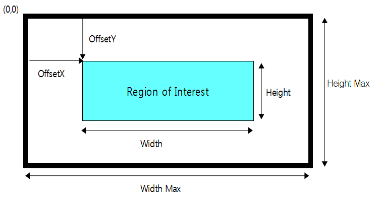
WidthMAX ≥ Offset X + Width HeightMAX ≥ Offset Y + Height
By setting Width, Height, Offset X, and Offset Y, the user can receive only the desired area. The frame rate increases as the image size becomes smaller.
ROI Setting
4.1.3 Binning Vertical
This function combines two vertical pixels so the frame rate becomes twice as fast.
4.1.4 Binning Horizontal Vertical
This function combines two horizontal pixels to increase the frame rate. It cannot be adjusted independently and can be additionally adjusted when Binning Vertical is enabled.
4.1.5 Decimation Vertical
This function skips every other vertical pixel so the frame rate becomes twice as fast.
4.1.6 Decimation Horizontal
This function skips every other horizontal pixel in the output to increase the frame rate.
Note: Model-specific Binning (Bin) and Decimation (Sub) support status
Image Mode
MC-A040x-523
MC-A160x-154
MC-A320x-55
MC-A500x-35 MC-A500M-LF
MC-A121x-20
MC-A121R/L-20
Binning Vertical
X
O (Only Mono)
X
X
X
X
Binning Horizontal Vertical
X
O (Only Mono)
X
X
X
X
Decimation Vertical
X
O
O
O
O
X
Decimation Horizontal
X
O
O
O
O
X
Note: Only MC-A160M-154 supports Binning Vertical and Binning Horizontal Vertical.
4.1.7 Reverse X, Y
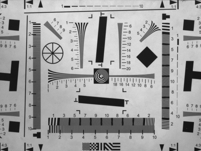
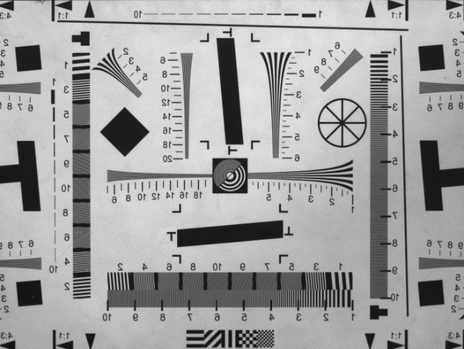
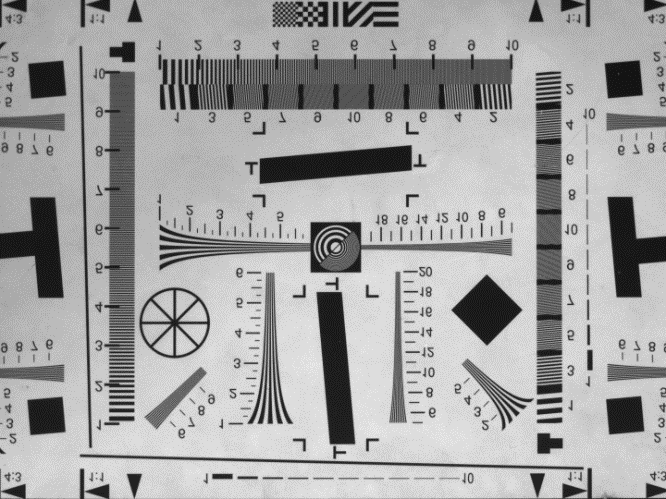
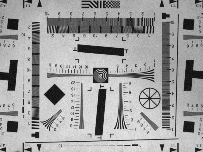
This function changes the left/right and top/bottom orientation of the image. In Reverse X mode, the image is flipped left/right; in Reverse Y mode, it is flipped top/bottom.
When Reverse Y is selected, use of the Defect Filter is limited and defective pixels may appear.
OriginalReverse XReverse YReverse X and Y
4.1.8 ADC Bit Depth
This function changes the bit depth of the image output from the sensor. It can be set to 8-bit, 10-bit, or 12-bit. (Excludes MC-A320x-55, MC-A500x-35, MC-A500M-LF, MC-A121x-20, and MC-A121R/L-20)
In 8-bit mode, the image is approximately four times brighter than in 10-bit or 12-bit mode.
4.1.9 Pixel Format
This function changes the format of the image output from the camera. Supported formats differ by model, so check the main specifications before setting it.
4.1.10 Test Pattern
Displays a test pattern image. Off shows the normal image, and On shows the test pattern.
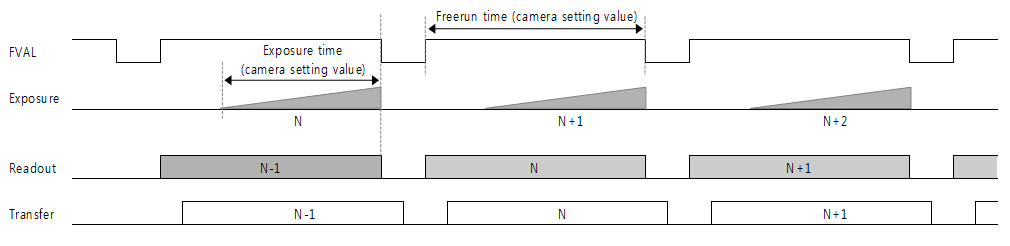
Off : The camera operates in Freerun mode. An internal trigger signal is generated, and its period is determined by Acquisition Frame Rate. If Acquisition Frame Rate Enable is Off, the camera runs at the maximum frame rate possible with the current settings.
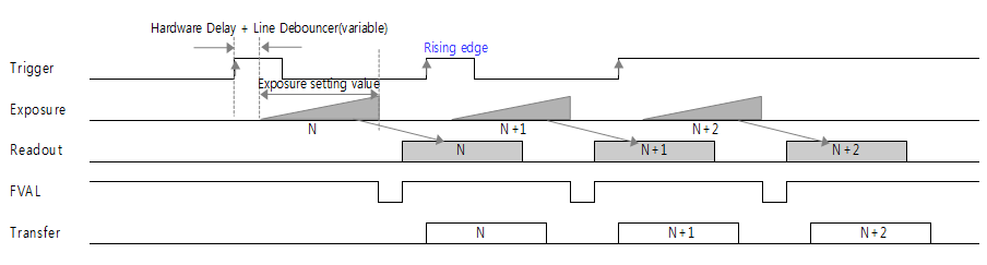
On : The camera operates in Trigger mode. Triggers can be input through CC1 to CC4 (Line1 to Line4), GPIO (Line5 to Line6), or Software Trigger from the Frame Grabber.
Selects the source to be used as the trigger input.
Trigger Delay
0x1 ~ 0xFFFFFFFF 0 ~ 57,844,677µs
Adjusts Trigger Delay. (TRGDLY)
Line Debounce Time
0x1 ~ 0xFFFF 0 ~ 882µs
Adjusts Line Debounce Time. (TRGFLTNUM)
4.2.2 Trigger Software
This applies when Trigger Mode is set to On and Trigger Source is set to Software. Executing it inputs one trigger pulse and acquires one image frame.
4.2.3 Trigger Source
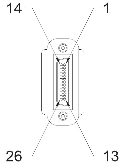
Camera Link Connector - Line1 to Line4: trigger input from the Frame Grabber through CC1 to CC4 pins.
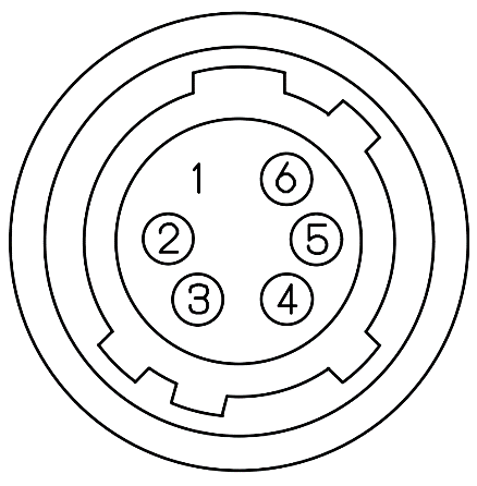
6pin Connector - Line5: trigger input through pin 2 (GPIO1), and Line6: trigger input through pin 3 (GPIO2).
Software Trigger - Generates a trigger through the software function.
4.2.4 Trigger Delay
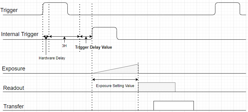
This function delays operation by the user-set delay time after trigger input. It can be adjusted in microseconds with the TRGDLY command.
Trigger Delay Timing
Note: 1H = 74.25 MHz (Global Model) or 72 MHz (Rolling Model) x HMAX. Check RHMAX command or CamGuideCL.
Note: Hardware Delay: < 2 us (see 4.3.1)
4.2.5 Line Debounce Time
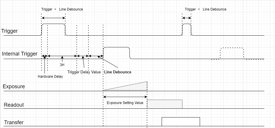
This function filters chattering noise in trigger signals transferred through external I/O. Trigger signals shorter than Line Debounce Time are treated as noise and filtered. It can be adjusted in microseconds with the TRGFLTNUM command.
Line Debounce Timing
4.2.6 Fine Shutter Enable (Unit Control)
This function supports exposure-time adjustment in 1 us units based on Pixel Clock. When On, exposure is adjusted in microseconds; when Off, it is adjusted in HD units.
4.2.7 Exposure Mode
This function determines the camera exposure method.
Mode
Description
Timed
Exposes for the configured time value.
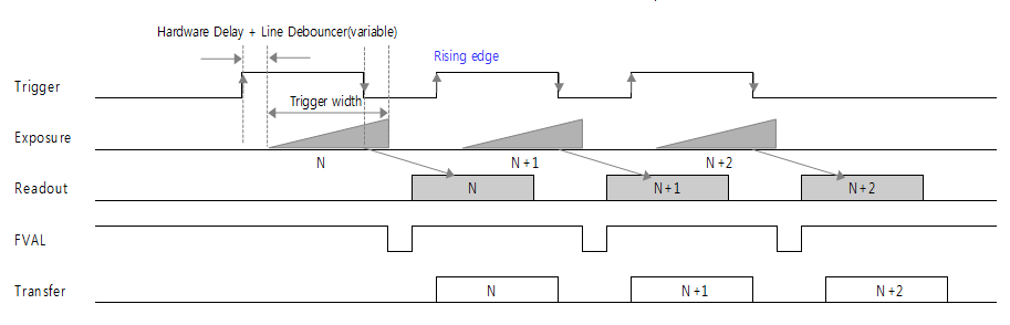
Trigger Width
Exposes for the pulse width of the input trigger signal. If Trigger Active is Rising Edge, exposure lasts while the signal is High; if Falling Edge, exposure lasts while the signal is Low.
Sets the exposure time. This applies only when Exposure Mode is set to Timed. It can be adjusted in microseconds with the SHTSET command. (Range: 0x1 to 0xFFFFFFFF)
Note: Actual exposure time = setting time + 14.26 us or 13.73 us (see 2.2 Main Specifications)
4.2.9 Exposure Auto
This function automatically adjusts Exposure Time to keep the brightness desired by the user. It can be used when Exposure Mode is set to Timed.
Item
Setting Value
Description
Exposure Auto
Off
Sets Exposure Time manually.
Once
Adjusts exposure time once to change the image to the desired brightness value.
Continuous
Continuously adjusts exposure time to maintain the desired brightness value.
Auto Exposure Target
0 ~ 255
Sets the desired brightness value (DN, based on 8-bit).
Auto Exposure Time Lower Limit
100µs ~ 3sec
Minimum automatically configurable Exposure Time (AEMIN). It cannot be greater than the Upper Limit.
Auto Exposure Time Upper Limit
100µs ~ 3sec
Maximum automatically configurable Exposure Time (AEMAX). It cannot be less than the Lower Limit.
Note: Exposure Time setting values may vary depending on Width and ADC Bit settings.
4.2.10 Acquisition Frame Rate Enable
Item
Setting Value
Description
Acquisition Frame Rate Enable
Off
Operates at the maximum frame rate available with the current camera settings.
On
Operates at the configured frame rate.
Acquisition Frame Rate
1 ~ Max Value
The maximum value differs by model and resolution.
Only Line 5 and Line 6 can be set as Output; Line Source is applied afterward.
Line Inverter
0, 1
When enabled, the input signal is inverted.
Line Status
0, 1
Returns the current state of the selected Line.
Line Source
Off
Not used
Timer1 Active
Outputs a waveform generated inside the camera.
Exposure Active
Active during the camera exposure time.
UserOutput1 / 2 / 3
Maintains the user-configured output value independently of Input.
User Output Selector
Selects the stored value to use.
User Output Value
0, 1
Sets the value selected by User Output Selector.
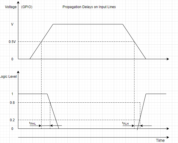
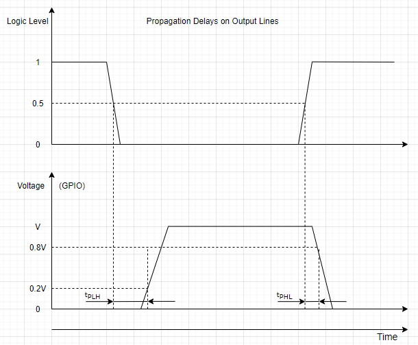
4.3.1 Hardware Propagation Delay (GPI/O)
Rising (tPLH) (<20%)
Falling (tPHL) (>80%)
Input Line
0.52µs
0.03µs
Output Line
1.34µs
0.17µs
Propagation Delays on Input LinesPropagation Delays on Output Lines
4.4 Counter and Timer Control
This function configures the strobe signal and checks image output.
Item
Setting Value
Description
Timer Selector
Exposure External Trigger Internal VD
Exposure: generates a waveform from the exposure start point. External Trigger: generates a waveform from the external trigger input point. Internal VD: generates a waveform from the internal VD start point.
Timer Duration
0 ~ 57,844,677
Sets the High time of the strobe signal. (FLASHTIME)
Timer Delay
0 ~ 57,844,677
Sets the Delay time of the strobe signal. (FLASHDELAY)
Selects and counts the number of external trigger inputs, exposure start/end counts, Sensor FVAL count, and abnormal exposure start/end counts.
Counter Value
0 ~ 4,294,967,295
Displays the Count value of Event Source. It is initialized at Acquisition Start.
Timer Duration - Adjusted in microseconds with the FLASHTIME command.
Timer Delay - Adjusted in microseconds with the FLASHDELAY command.
4.5 Analog Control
4.5.1 Gain Control
This function adjusts Gain.
Item
Setting Value
Description
Gain Selector
All, DigitalAll
Selects the Gain to configure.
Gain Raw
All : 0 ~ 240 Rolling Model : 65535 ~ 1474537 DigitalAll : 0 ~ 7168
Applies the Gain value numerically. Image signal and noise may increase together.
Gain Abs
All : 1 ~ 15.8 Rolling Model : 1 ~ 22.49 DigitalAll : 1 ~ 8.0
Applies the Gain value as a multiplier.
Gain Auto
Off
Sets Gain manually.
Once
Adjusts Gain once to change the image to the desired brightness.
Continuous
Continuously adjusts Gain to maintain the desired brightness.
When Gain Auto and Auto Exposure are used together, Exposure Control is applied first when the image becomes brighter, and Gain Control is applied first when the image becomes darker.
4.5.2 Black Level Control
This function adjusts the DC offset of the image signal.