Analog : 0 ~ 255 (8bit), 0 ~ 1023 (10bit), 0 ~ 4095 (12bit) Digital : 0 ~ 4095 (12bit)
Auto Gain / Exposure
Off / Once / Continuous
Gamma / LUT
Gamma 0 ~ 3.999 / Adjustable LUT (12bit to 12bit)
Video I/F
CameraLink / SDR x1
Video Format
Mono 8, Mono 10, Mono 12
Communication
RS232 via CameraLink Connector
Function Control
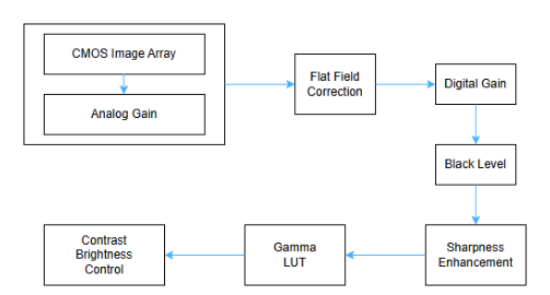
Gain Auto, Exposure Auto, Acquisition Frame Rate(Adjustable), Line Debouncer, Defect Pixel Correction, Shading Correction(FFC), Sharpness Enhancement, Contrast/Brightness Control, Sensor Cooling Control
GPIO
TTL Input/Output 2ch, OptoCoupled Input 2ch
Lens Mount
C mount
Optical Filter
900nm Long Pass
Power Supply
DC(12V ~ 24V ± 10%)
Consumption (Typical)
5.0W
Weight
< 400g
Dimension
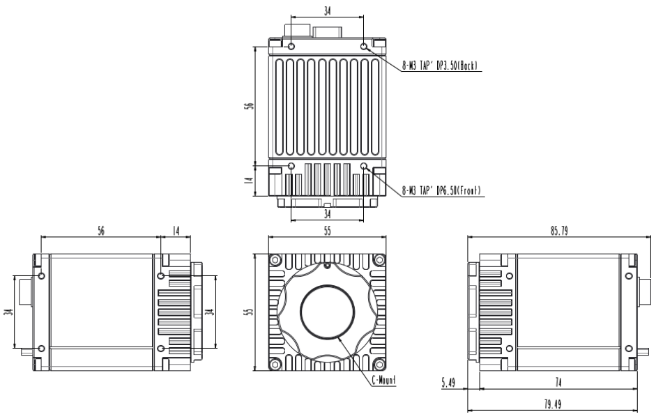
55 x 55 x 74 ㎜ (Without Mount, Connector)
Operating / Storage
0℃ ~ +40℃ / -20℃ ~ +60℃ (with < 20~80% RH)
Vibration / Shock
98 m/s2 (10.0 G) / 196 m/s2 (20.0 G)
Standard Compliancy
CE (EN61326-1; 2013; Class A)
Environments
RoHS / WEEE
3. Camera exterior specifications
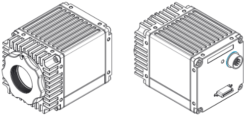
3.1 Appearance
HC-A130SW
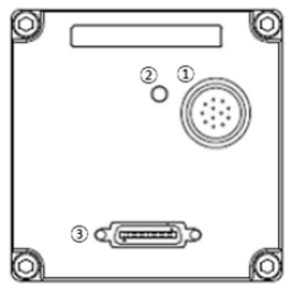
3.2 Back Panel
No.
Name
etc
1
Power & I/O Connector
12Pin Circular Connector
2
LED Indicator
LED
3
CameraLink Connector
Base (SDR Type)
3.3 LED Indicator Status
Indication
State
Off
No power
Solid orange
System booting
Solid green
Device – Host connected, but no data being transferred
Blinking green
Data being transferred
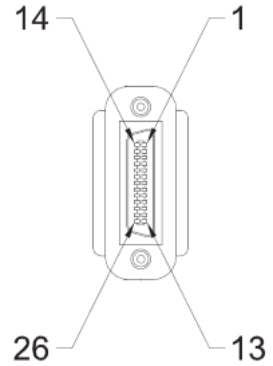
3.4 CameraLink Connector
3.4.1 CameraLink Connector1 (SDR Type)
Pin No.
Signal Name
Pin No.
Signal Name
1
PoCL1
14
GND
2
X0-
15
X0+
3
X1-
16
X1+
4
X2-
17
X2+
5
Xclk-
18
Xclk+
6
X3-
19
X3+
7
SerTC+
20
SerTC-
8
SerTFG-
21
SerTFG+
9
CC1-
22
CC1+
10
CC2+
23
CC2-
11
CC3-
24
CC3+
12
CC4+
25
CC4-
13
GND
26
PoCL1
3.5 External I/O Connector
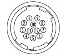
3.5.1 Circular Connector (12Pin)
Pin No.
Name
IN/OUT
Description
1
GND
IN
Power GND
2
VCC
IN
12V ~ 24V Input Range
3
Line 7(-)
IN
OptoCoupled Trigger Input-
4
Line 7(+)
IN
OptoCoupled Trigger Input+, 3.3V~24V
5
Line 6(-)
IN
OptoCoupled Trigger Input-
6
Line 6(+)
IN
OptoCoupled Trigger Input+, 3.3V~24V
7
Line 4
IN/OUT
Direct IO, 3.3V
8
DGND
IN
Direct IO GND
9
NC
-
Do not Connect
10
Line 5
IN/OUT
Direct IO, 3.3V
11
VCC
IN
12V ~ 24V Input Range
12
GND
IN
Power GND
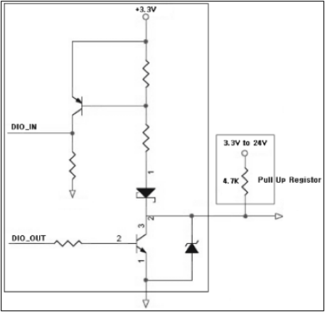
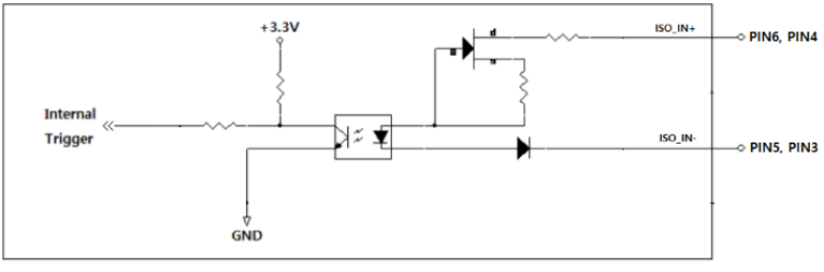
3.6 External I/O internal circuit
3.6.1 Line 4, 5 (Direct IO)
3.6.2 Line 6, 7 (OptoCoupled Input)
3.7 CameraLink Interface Timing
3.7.1 Mono or Color Bayer Order
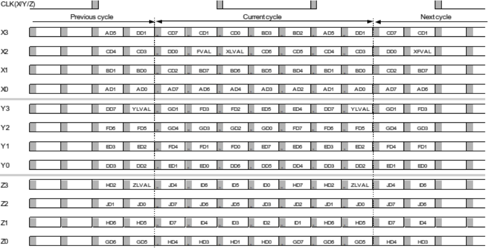
3.7.2 Data Order of the CameraLink
4. Camera Functions
4.1 Image Format Control
4.1.1 Device Tap Geometry
This is the function to set Device Tap Geometry. The HMax value that determines the Line Period changes depending on the Tap setting. HMax is the number of clocks based on 74.25MHz.
Feature
Value
Description
Command
HMax
(Read Only)
1 Outputs the number of clocks in the line period.
RHMAX
Device Tap Geometry
1X_1Y
Set the number of data transmission taps on the CL Interface.
R/WTAPCFG
1X2_1Y
1X3_1Y
*1 Line Period(us) = 1/74.25 * 'HMax'
*For normal images to be output, the camera tap settings and the Frame Grabber Camfile tap settings must be the same.
4.1.2 ROI (Region Of Interest)
ROI
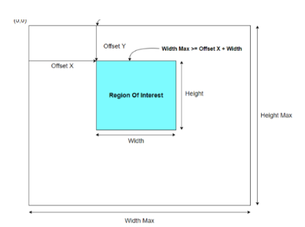
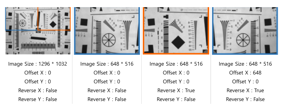
By setting Width, Height, Offset X, and Offset Y, you can output only the image of the desired area. As the output height size gets smaller, the frame rate increases.
< Figure 1 – ROI Setting >
Feature
Value
Description
Command
WidthMax
(Read Only)
This is the maximum output size of the Image.
RWIDTHMAX
HeightMax
(Read Only)
This is the maximum output size of the Image.
RHEIGHTMAX
Width
(Integer)
Change the output size and offset (pixel coordinates) of the image. WidthMax ≥ Offset X + Width HeightMax ≥ Offset Y + Height
R/WWIDTH
Height
(Integer)
Change the output size and offset (pixel coordinates) of the image. WidthMax ≥ Offset X + Width HeightMax ≥ Offset Y + Height
R/WHEIGHT
Offset X
(Integer)
Change the output size and offset (pixel coordinates) of the image. WidthMax ≥ Offset X + Width HeightMax ≥ Offset Y + Height
R/WOFFSETX
Offset Y
(Integer)
Change the output size and offset (pixel coordinates) of the image. WidthMax ≥ Offset X + Width HeightMax ≥ Offset Y + Height
R/WOFFSETY
*The Frame Rate changed due to ROI can be checked through the ‘Resulting Frame Rate’ and the Line Period through the ‘HMax’ Feature.
*However, if 'Exposure Time' is longer than Frame Period (=1/Max.FrameRate), the Frame Rate may decrease. (Exposure priority mode)
*The characteristics of 'Width' and 'Height' for each model are as follows.
Model
Minimum Width
Minimum Height
Width Unit
Height Unit
All models
64
32
8
4
< Table 1 – Minimum & Unit Size of ROI >
4.1.3 Binning
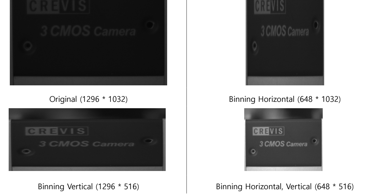
This is a function that cumulatively reads adjacent pixels in the horizontal or vertical direction. While it has the same resolution as decimation, binning can increase sensitivity by about twice because video signals are added. Because digital binning is applied, the frame rate does not increase, but if ROI is applied together, the frame rate may increase.
< Figure 2 – Binning(Sum) Image >
Feature
Value
Description
Command
Binning Horizontal Mode / Binning Vertical Mode
Average
Choose how to stack adjacent pixels. - Average: Output the average value of adjacent pixels
R/WBENMODE
Sum
- Sum: Output the sum of adjacent pixels
Binning Horizontal / Binning Vertical
1
The resolution of the image is reduced and adjacent pixels are accumulated and output. - 1: Original Image output
R/WBEN
2
- 2: Binning Image output
*However, if 'Exposure Time' is longer than Frame Period (=1/Max.FrameRate), the Frame Rate may decrease. (Exposure priority mode)
4.1.4 Decimation
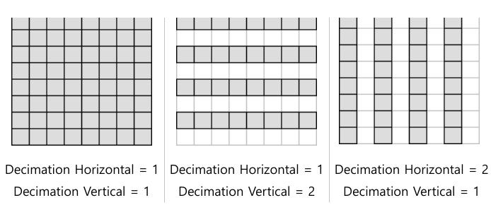
This is a function that reads quickly from the sensor, skipping 1 pixel in the horizontal or vertical direction. The resolution of the image is reduced by half, while the frame rate is increased.
< Figure 3 – Decimation >
Feature
Value
Description
Command
Decimation Horizontal / Decimation Vertical
1
The image resolution decreases and the frame rate increases. - 1: Original Image output
R/WSKIP
2
- 2: Decimation Image output
*The Frame Rate changed due to Decimation can be checked through the ‘Resulting Frame Rate’ Feature.
*However, if 'Exposure Time' is longer than Frame Period (=1/Max.FrameRate), the Frame Rate may decrease. (Exposure priority mode)
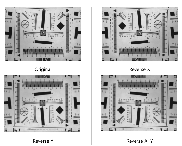
4.1.5 Reverse
< Figure 4 – Reverse Image >
Feature
Value
Description
Command
ReverseX / ReverseY
True
The image is flipped left/right or up/down.
R/WFLIPMODE
False
*When ROI and Reverse are used simultaneously, the ROI function is applied from the reversed image. In other words, when Reverse is activated as shown below, the position of the (0,0) Pixel, which is the starting coordinate of the Image, is reversed. Because of this, the same area as before applying Reverse
< Figure 5 – ROI & Reverse Image >
4.1.6 ADC Bit Depth
This is a function to set the bit depth when converting data from sensor to digital. The Max Frame Rate varies depending on the ADC Bit Depth setting, and in the same environment, the brightness of the video in 8bit mode is about 4 times brighter than the brightness of the video in 10bit and 12bit mode.
Feature
Value
Description
Command
ADC Bit Depth
8bit
Select Digital Data Depth of Sensor.
R/WADCBIT
10bit
12bit
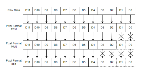
4.1.7 Pixel Format
Set the Pixel Format of the image output from the camera. Since the amount of image transmission varies for each pixel format, the frame rate may change depending on the bandwidth.
Feature
Value
Description
Command
Pixel Format
Mono 8
Set the format of the image data to be transmitted to the Frame Grabber.
R/WPIXFMT
Mono 10
Mono 12
*The format of image data cannot be larger than the ‘ADC Bit Depth’ of the sensor.
*The 'Pixel Format' supported for each model is as follows.
Model
Pixel Format Support
All models
Mono 8, Mono 10, Mono 12
< Table 2 – Pixel Format Values >
< Figure 6 – Pixel Format >
4.1.8 Test Pattern
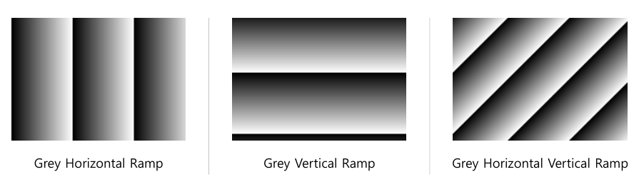
At the intermediate stage of image processing, the image is replaced with a test pattern and transmitted. Even if the Test Pattern function is activated, functions related to image acquisition such as ROI Size, Trigger Input, and Acquisition Frame Rate are valid. Test Pattern Image is created in 8bit gray level (0~255DN).
< Figure 7 – Test Pattern Image >
Feature
Value
Description
Command
Test Pattern
Off
Select Test Image. - Off: Sensor Image output
R/WOUTSEL
Grey Horizontal Ramp
- Gray Horizontal Ramp: Image output with brightness increasing horizontally
Grey Vertical Ramp
- Gray Vertical Ramp: Image output with brightness increasing vertically
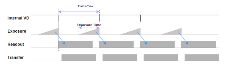
Controls image acquisition method and timing. image acquisition methods include Freerun Mode (Trigger Mode = Off) and Trigger Mode, and the acquisition delay can be set.
When Trigger Mode is Off, the camera operates in Freerun Mode. Freerun Mode generates Internal Counter and VD signals based on the maximum frame rate that can operate in the current settings. At the same time, an exposure signal is generated for the set exposure time to operate the sensor, acquire the image, and transmit it to the frame grabber.
< Figure 8 – Freerun Mode >
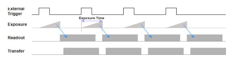
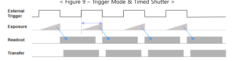
When Trigger Mode is On, the camera operates in Trigger Mode. Trigger Mode starts exposure with an External Trigger and can also adjust the exposure time. After the sensor completes exposure, the image is acquired and transmitted to the frame grabber in the same way as in freerun mode.
- Line 1 ~ 3 (CC1 ~ 3): Trigger created by Frame Grabber
R/WTRGSRC
Line 4 ~ 7
- Line 4 ~ 7: External Trigger using 12Pin Circular Connector (refer to 3.5 External I/O Connector)
Software
- Software: Trigger created inside the camera by Trigger Software Command
*In Freerun Mode, if 'Acquisition Frame Rate Enable' is 'On', it operates at 'Acquisition Frame Rate', and if 'Off', it operates at the maximum frame rate that can operate in the current settings.
*When 'Trigger Mode' is 'On', it operates by CC, External Trigger, or Software Trigger according to the 'Trigger Source' setting.
*CC1~3 must be set separately in the Frame Grabber program.
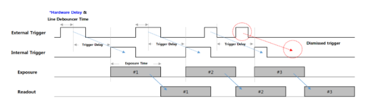
*If you set the 'Counter Event Source' in the 'Counter And Timer Control' category to 'External Trigger Start', the total number of valid triggers entered by the camera will be output as 'Counter Value'. You can update the current Counter in real time by ‘Execute’ the ‘Counter Update Feature’. This Counter is initialized to 0 by 'Execute' 'Counter Reset'. Trigger Delay is a function that operates by delaying the sensor's exposure for a certain period of time from the trigger input. When the timing of the camera input trigger does not match the timing of the external environment, such as lighting or the location of the subject, you can use Trigger Delay to obtain a clearer image. Line Debounce Time is a function that removes chattering noise of the trigger signal passing through external I/O. Since only signals that remain activated for more than a certain period of time are judged as valid inputs, delayed
< Figure 11 – Trigger Delay & Line Debounce >
Feature
Value
Description
Command
Trigger Delay
0 ~ 57,844,677 (Unit : us)
Set the delay time from trigger input to sensor exposure.
R/WTRGDLY
Line Debounce Time
0 ~ 882 (Unit : us)
Set the Line Debounce Time.
R/WTRGFLTNUM
*New triggers entered while the trigger is delayed are ignored. If the 'Trigger Delay' is larger than the input trigger period, the frame rate may decrease due to missing trigger. (See Figure 11)
*There is a certain amount of time delay (Hardware Delay + Exposure Start Delay) from the external trigger input to the actual exposure of the sensor. (Refer to Appendix B, C)
4.2.2 Exposure Control
Set the camera exposure method. When the exposure start time is determined by the Internal Freerun Counter or External Trigger, Timed Shutter exposes for the time set in Exposure Time, and Trigger Width Shutter exposes for as much as the trigger's pulse width in Trigger Mode. Exposure Time only applies when Exposure Mode is Timed Shutter.
Feature
Value
Description
Command
Fine Shutter Enable
Off
- Off: Adjust Exposure Time in 1 line units
R/WHRSTMODEEN
On
- On: Adjust Exposure Time in 1 us units
Exposure Mode
Timed
- Timed: Adjust exposure time by setting Exposure Time
R/WEXPMODE
Trigger Width
- Trigger Width: Adjust exposure time with the pulse width of the external trigger
Exposure Time
7 ~ 3,000,000 (Unit : us)
Set the exposure time for Timed Shutter.
R/WSHTSET
*However, if 'Exposure Time' is longer than Frame Period (=1/Max.FrameRate), the Frame Rate may decrease. (Exposure priority mode)
*If 'Trigger Mode' is 'Off' or 'Trigger Source' is 'Software', it operates as a 'Timed' Shutter.
*If you set 'Counter Event Source' in the 'Counter And Timer Control' category to 'Exposure Start' or 'Exposure Stop', the actual start and end times of exposure are output as 'Counter Value'. You can update the current Counter by ‘Execute’ the ‘Counter Update Feature’. This Counter is initialized to 0 by the 'Counter Reset' Command.
*There is a certain amount of time delay (Hardware Delay + Exposure Start Delay) from the external trigger input to the actual exposure of the sensor. (Refer to Appendix B, C)
*There is an error (Exposure Offset) between 'Exposure Time' and the actual exposure time. (Refer to Appendix C) Exposure Auto is a function that allows the camera to automatically adjust the Exposure Time to obtain an image with the desired brightness. It can only be used when the Exposure Mode is Timed.
Feature
Value
Description
Command
Exposure Auto
Off
- Off: Set Exposure Time manually
R/WAECMODE
Once
- Once: Turn Exposure Auto Off when the image reaches the target brightness
Continuous
- Continuous: Continuously adjust Exposure Time to maintain the target brightness
Auto Exposure Target
0 ~ 255 (DN @8bit)
Set the desired average brightness.
R/WAETARGET
Auto Exposure Time Lower Limit
100 ~ 3,000,000 (Unit : us)
When using Exposure Auto, set the variable range of Exposure Time. Lower Limit ≤ Upper Limit_ _
R/WAEMIN
Auto Exposure Time Upper Limit
R/WAEMAX
Exposure Update Feature
Execute
Update Exposure Time.
-
*However, if 'Exposure Time' is longer than Frame Period (=1/Max.FrameRate), the Frame Rate may decrease. (Exposure priority mode)
*When using 'Exposure Auto' and 'Gain Auto' at the same time, the operation varies depending on the brightness of the Image and Target.
*If the brightness of the image needs to be increased, 'Gain Auto' is applied after applying 'Exposure Auto'.
*If the brightness of the image needs to be reduced, 'Exposure Auto' is applied after applying 'Gain Auto'.
4.2.3 Frame Rate Control
This is a function to control the frame rate in freerun mode.
Feature
Value
Description
Command
Acquisition Frame Rate Enable
Off
Determines whether to activate the Acquisition Frame Rate function in Freerun Mode.
R/WFREERUNEN
On
Acquisition Frame Rate
1 ~ Max.FPS
Set the desired Frame Rate in Freerun Mode.
R/WFREERUN
Resulting Frame Rate
(Read Only)
In Freerun Mode, the frame rate of the actual camera is output.
REALFREERUN
*Max.FPS changes depending on the 'Device Tap Geometry', ROI, Decimation, 'Pixel Format', and 'Exposure Time' settings.
*Freerun Mode is ‘Trigger Mode’ = ‘Off’.
4.3 Digital I/O Control
This function sets external I/O signals. You can change Input/Output and phase by selecting the Line you want to set.
Feature
Value
Description
Command
Line Selector
Line 1 ~ 7
Select the Line for which you want detailed settings. - Line 1~3 : CC1~3 - Line 4, 5 : Direct I/O - Line 6, 7 : OptoCoupled Input
-
Line Mode
Input
Lines 1~3, 6, and 7 only allow input settings.
R/WLINEMODE
Output
Lines 4 and 5 can be set as Input/Output.
Line Inverter
True
- True: Line input/output phase 180o conversion
R/WLINEINVEN
False
- False: Maintain input/output phase of line
Line Status
(Read Only)
Outputs the current status of the selected line.
RLINESTATUS
Line Status Update Feature
Execute
Updates the current status of all lines.
-
*If 'Exposure Mode' is 'Trigger Width', 'Line Inverter' may affect the brightness of the image.
*In the case of 'Line Status', 'True' is Logical High, and 'False' is Logical Low.
*If the I/O Connector is not connected and is in a floating state, 'Line Status' outputs 'True'.
*'Line Selector' is included in the commands of Mode, Inverter, Status, and Source. (Ex. WLINEMODE 4 1, RLINEINVEN 1, RLINESTATUS 3, WLINESRC 5 2)
Feature
Value
Description
Command
Line Source
Off
Select the waveform to output as a strobe signal. - Off : Strobe Off
R/WLINESRC
Timer 1 Active
- Timer 1 Active: Timer Strobe signal output (refer to 4.4.1 Timer Control)
Exposure Active
- Exposure Active: Strobe signal output active during actual exposure time
User Output 1~3
- User Output 1~3: Output User Output Value as the strobe signal
User Output Selector
User Output 1~3
Select the User Output you want to set.
-
Feature
Value
Description
Command
User Output Value
True
- True: Set the selected User Output to High.
R/WUSEROUTPUT
False
- False: Set the selected User Output to Low.
*'User Output Selector' is included in the Value Command. (Ex. WUSEROUTPUT 1 1, RUSEROUTPUT 3)
4.4 Counter And Timer Control
4.4.1 Timer Control
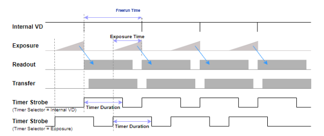
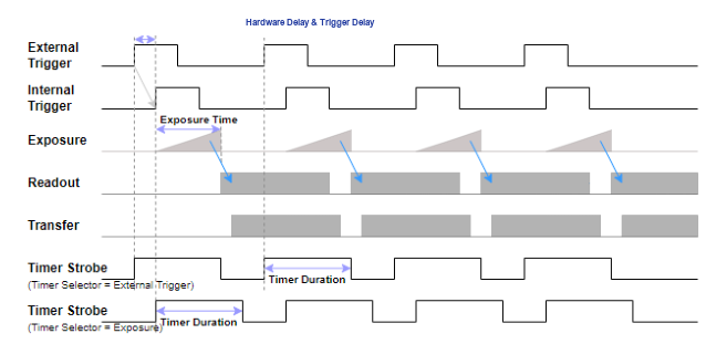
This is the function to set the strobe signal output outside the camera. In Freerun Mode, the Timer Strobe signal generation point can be set to the exposure start or Internal VD Start point. The point at which the VD is initialized is Shutter
< Figure 12 – Timer Strobe of Freerun Mode >
In Trigger Mode, the generation point of the Timer Strobe signal can be set to the start of exposure or the point of external trigger input. When creating a Timer Strobe at the time of External Trigger input, Trigger Delay and Hardware
< Figure 13 – Timer Strobe of Trigger Mode >
Feature
Value
Description
Command
Timer Selector
Exposure
Select when to start Timer Strobe. - Exposure: Timer Strobe output based on the actual exposure start point
R/WFLASHSRC
External Trigger
- External Trigger: Timer Strobe output based on the trigger input time
Internal VD
- Internal VD: Timer Strobe output based on the Internal Counter Reset point
Timer Duration
0 ~ 57,844,677 (Unit : us)
Set the Pulse Width of Timer Strobe.
R/WFLASHTIME
Timer Delay
0 ~ 57,844,677 (Unit : us)
Set the Timer Strobe output delay time from the selected start point.
R/WFLASHDELAY
*In Trigger Mode, the Internal Counter does not operate, so 'Internal VD' cannot be used.
4.4.2 Counter Control
This function monitors camera movement. The process of the camera receiving a trigger, exposing, and outputting an image can be monitored with a step-by-step counter. Additionally, it is possible to check for signal input that exceeds camera specifications, such as trigger input at a speed faster than the frame cycle.
Feature
Value
Description
Command
Counter Event Source
External Trigger Start
Select Counter. - External Trigger Start: Number of External/Software Trigger inputs
RTRGSTARTCNT
Exposure Start
- Exposure Start: Exposure start count
REXPSTARTCNT
Exposure End
- Exposure End: Exposure end count
REXPENDCNT
Frame End
- Frame End: Number of Readout Frames
FRAMEENDCNT
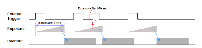
Exposure Start Missed
- Exposure Start Missed: Number of trigger inputs during exposure
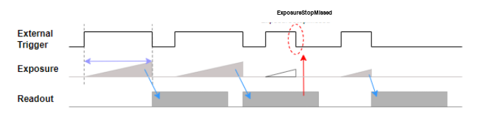
REXPSTARTMISSCNT
Exposure Stop Missed
- Exposure Stop Missed: Number of exposure stop events during readout
REXPENDMISSCNT
Counter Value
(Read Only)
Outputs the value of the selected counter.
-
Counter Reset
Execute
Initializes the value of all counters to 0.
WRESETCNT
Counter Update Feature
Execute
Update Counter Value.
-
*'Exposure Start Missed' can increase when 'Trigger Mode' = 'On' and 'Exposure Mode' is 'Timed'.
Determines whether to activate the Gamma function.
R/WGAMMAEN
False
Gamma
0 ~ 3.99
Set Gamma.
R/WGAMMA
*The Gamma function cannot be used simultaneously with the LUT function. When the Gamma function is enabled, the LUT function is disabled.
4.6 LUT Control
The LUT (Look Up Table) function is a function that converts digital pixel values by matching them 1:1 to the output value of the table's input value. Each Index (Input Image) in the table is replaced with a pixel of a predefined LUT Value (Output Image).
Feature
Value
Description
Command
LUT Enable
True
Determines whether to activate the LUT function.
R/WLUTEN
False
LUT Index
0 ~ 4095
Select LUT Index.
R/WLUTDATA
LUT Value
0 ~ 4095
Set the output value of the selected LUT Index.
*The LUT function cannot be used simultaneously with the Gamma function. When the LUT function is enabled, the Gamma function is disabled.
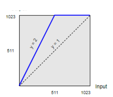
*Ex) When using a table in the form of y=2x, low-illuminance pixels can see an improvement in sensitivity, while high-illuminance pixels become saturated, resulting in loss of dynamic range.
Index
0
1
2
3
...
256
...
510
511
512
513
Value
0
2
4
6
…
512
...
1022
1023
1023
1023
< Figure 18 – Look Up Table Graph >
4.7 Defect Pixel Control
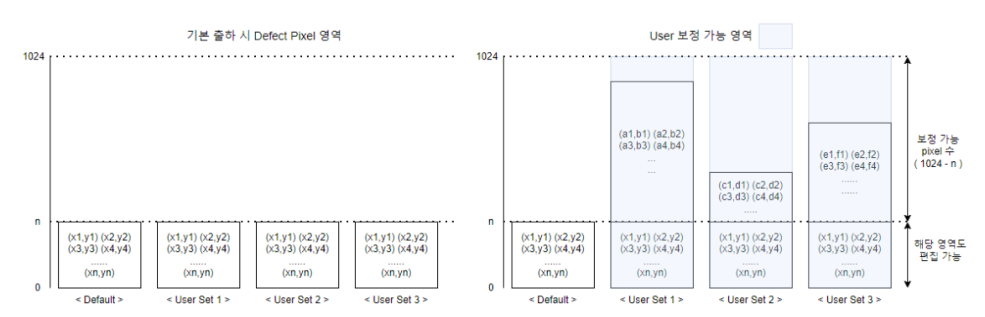
This function manages the camera’s defect pixels. Correction is made for defective pixels at the time of shipment. However, you can compensate by additionally defining pixels that the user considers to be bad pixels. Up to 1024 defective pixels can be saved in each User Set 1 to 3 area of the camera.
Feature
Value
Description
Command
DefectFilter Enable
Off
Decide whether to activate the Defect Filter function.
R/WDEFCOREN
On
Feature
Value
Description
Command
Defectfilter Test Mode Selector
Off
This function is used to check the position of the pixel to which the Defect Filter has been applied. - Off: Sensor Image output
R/WDEFHIGHLIGHT
Mark Black
- Mark Black: Marks defect pixels as dark pixels.
Mark White
- Mark White: Displays defect pixels as white pixels.
Mark White with Black Background
- Mark White with Black Background: Marks defect pixels as white pixels. (Black Background)
Defect Pixel Replacement Count
1 ~ 1024
This is the number of defect pixels to be corrected.
R/WDEFCNT
Defect Pixel Index
0 ~ 1023
Index of the defect pixel to be corrected.
R/WDEFCORR
Defect Pixel X Coordinate
0 ~ WidthMax-1
This is the X-axis coordinate of the defect pixel to be corrected. Pixel coordinates start from 0.
Defect Pixel Y Coordinate
0 ~ HeightMax-1
This is the Y-axis coordinate of the defect pixel to be corrected. Pixel coordinates start from 0.
Defect Pixel Replace Execute
Execute
Applies the entered Defect Pixel information.
WDEFEXEC WIMMDEFCOR
*Ex) When the user adds two pixels while 20 defect pixels have been corrected at the time of product shipment.
DefectPixel ReplaceCount
DefectPixel Index
DefectPixel XCoordinate
DefectPixel YCoordinate
Remarks
19
18
...
...
Factory Defined
20
19
...
...
Factory Defined
21
20
(156, 31)
(1131, 125)
User Defined
22
21
(208, 114)
(321, 611)
User Defined
< Table 6 – User Define Example >
*After correction, save the data to the desired User Set area using the 'UserSetSave' command.
< Figure 19 – Defect Pixel Access Area >
4.8 Flat Field Correction
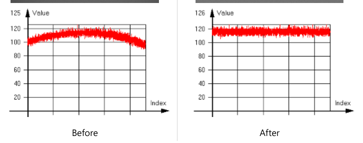
Flat Field Correction (FFC) is a function that uniformly corrects the brightness value of the captured image. Causes of uneven brightness values include the influence of lens shadows, uneven lighting brightness, and differences in sensitivity of each Sensor Pixel.
Feature
Value
Description
Command
FFC Enable
Off
Determines whether to enable the FFC function.
R/WFFCEN
On
Black Calibration
Execute
Perform Black Calibration.
WBLACKCAL
White Calibration
Execute
Perform white calibration.
WWHITECAL
FFC User Selector
0 ~ 3
Select an area to save/load FFC Data.
-
FFC Save
Execute
FFC Data is saved in the selected Flash area.
WFFCSAVE
FFC Load
Execute
Loads FFC Data from the selected Flash area.
WFFCLOAD
FFC Abort
Execute
Forcefully cancels the FFC function currently being performed.
WFFCABORT
FFC Process Status
(Read Only)
You can check the operation status of the FFC Function. - Complete: FFC Function completed - Get Black Image: Obtaining Black Image - Get White Image: Acquiring White Image - Black Calibrating: BlackCalibration in progress - White Calibrating: WhiteCalibration in progress - FFC Erasing: Deleting FFC Data - FFC Saving: Saving FFC Data - FFC Loading: Loading FFC Data
RFFCSTAT
FFC Update Feature
Execute
Update FFC Process Status.
-
*The FFC methods supported by model are as follows.
Model
FFC
All models
Pixel by Pixel
< Table 7 – FFC Mode >
*To stabilize power consumption and temperature, when the FFC function is disabled, FFC-related functions do not operate. After changing 'FFC Enable' to 'On', you must perform Calibration, Save, Load, etc.
*Defect Correction must be performed before FFC, and calibration must be performed under the condition that the Defect Filter is enabled to output an accurate corrected image.
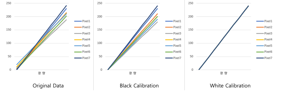
*'Black Calibration' must precede 'White Calibration', and 'Black Calibration' is performed before product shipment. By performing 'White Calibration' in an actual use environment (lens, etc.), differences in image brightness can be corrected, and if necessary, the user can proceed again from 'Black Calibration'.
*'FFC User Selector' is included in the Save and Load commands. (Ex. WFFCSAVE 0, WFFCLOAD 2)
< Figure 20 – FFC Calibration Graph >
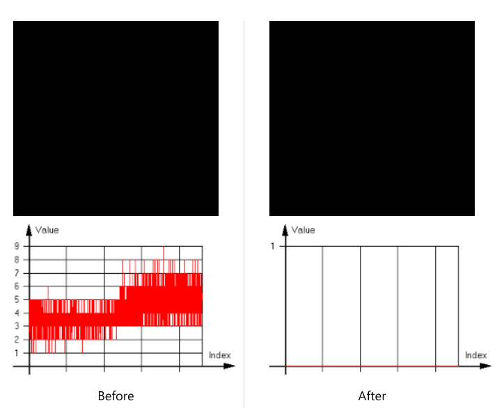
Black Calibration corrects the image in an environment with zero light level (shielded).
< Figure 21 – Black Calibration Image & Histogram >
White Calibration acquires and corrects bright images from actual use environments (lenses, etc.). By capturing a subject (or lighting) with uniform brightness, the difference in brightness caused by edge shading of the sensor or other external environments is corrected with an image of less than 200 DN on average, as shown in the graph below.
< Figure 22 – White Calibration Image & Histogram >
4.9 Sharpness Enhancement
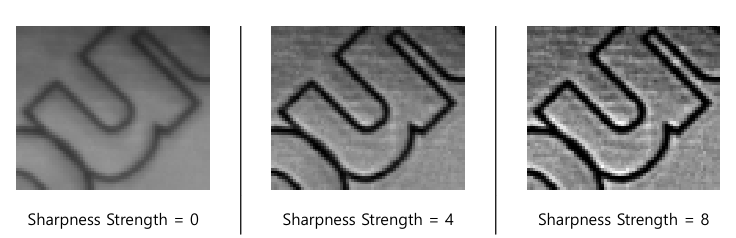
Sharpness Enhancement is a function that emphasizes the outlines in an image and makes them sharper. Depending on the Sharpness Enhancement setting, you can obtain a clearer image, but noise may also be emphasized.
Feature
Value
Description
Command
Sharpness Enable
Off
Determines whether to enable the Sharpness feature.
R/WSHARPEN
On
Sharpness Strength
0 ~ 15.996
Sets the intensity of Sharpness Enhancement.
R/WSHARPSTR
Sharpness Filter Size
0.001 ~ 4
Set the Sharpness Enhancement Filter Size.
R/WSHARPSIZE
*Ex) Sharpness Filter Size = 1.5
< Figure 23 – Sharpness Enhancement >
4.10 Contrast Brightness Control
4.10.1 Contrast
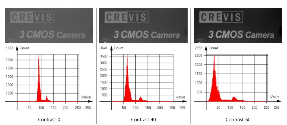
Contrast adjusts the contrast of the image.
< Figure 24 – Contrast >
Feature
Value
Description
Command
Contrast
-99 ~ 99
Adjust Contrast.
R/WCONTRAST
4.10.2 Brightness
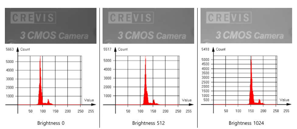
Brightness adjusts the brightness of the image. The setting value of 512 (based on 12 bit) increases the brightness by approximately 32 DN in an 8 bit video.
< Figure 25 – Brightness >
Feature
Value
Description
Command
Brightness
-2047 ~ 2047 (Unit : 12bit DN)
Adjust Brightness.
R/WBRIGHTNESS
4.10.3 Histogram Stretch
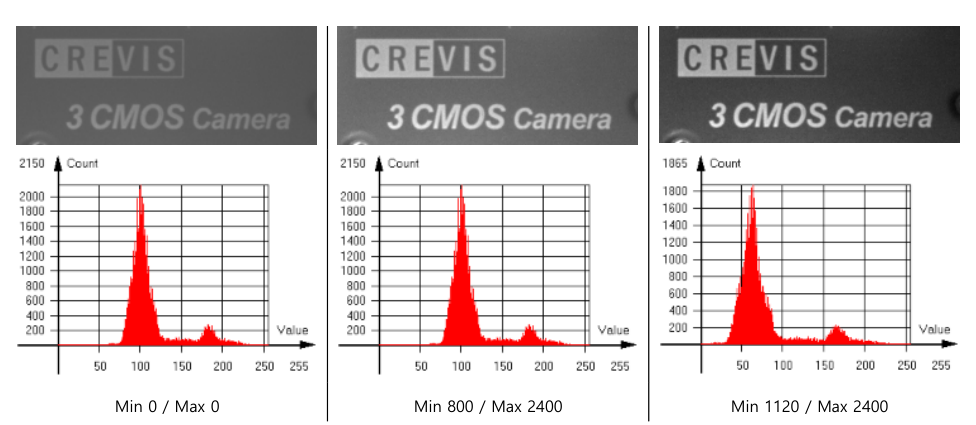
You can correct the image using Histogram Stretch. If Histogram Stretch Min is set to 800, the setting value of 800 (based on 12 bit) is about 50 DN in an 8-bit video, so 50 DN is stretched to 0 DN and the video is output. When Histogram Stretch Max is set to 2400, the setting value of 2400 (based on 12bit) is about 150DN in 8bit video.
Set the Max value of the Histogram. The brightness corresponding to the setting value is stretched to 4095.
R/WCBMAX
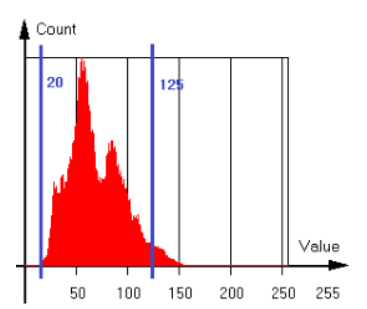
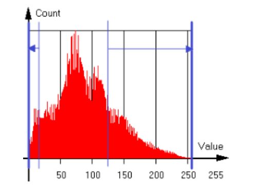
*Ex) When Min = 320, Max = 2000 are set, 20DN and 125DN based on 8 bits are stretched to 0DN and 255DN, respectively.
< Figure 27 – Histogram of Original Image >< Figure 28 – Histogram of Min, Max Control >
4.10.4 Auto Contrast
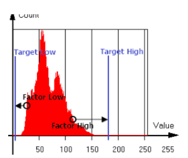
Auto Contrast is a function that automatically corrects the image by setting the factor and target. It corrects the image by stretching the factor setting value to the target setting value. Factor Low and Factor High are the lower and upper percentage values of all pixels in the image, respectively, and Target Low and Target High are 12-bit DN values (0 to 4095).
< Figure 29 – Histogram of Auto Contrast >
Feature
Value
Description
Command
Auto Contrast Mode
Off
- Off: Manually set Contrast and Brightness
R/WCBAUTOMODE
Once
- Once: Turn Auto Contrast Off when each factor reaches the target brightness
Continuous
- Continuous: Continuously adjust Contrast and Brightness to maintain the image
Auto Contrast Factor Low
0 ~ 50 (Unit : %)
Set the Auto Contrast Factor Low value. This is the bottom percentage of total pixels in the video.
R/WCBAUTOPLO
Auto Contrast Factor High
0 ~ 50 (Unit : %)
Set the Auto Contrast Factor High value. The top percentage of total pixels in the video.
R/WCBAUTOPHI
Auto Contrast Target Low
0 ~ Auto Contrast Target High-10 (Unit : 12bit DN)
Set the Auto Contrast Target Low value. Auto Brightness (DN) corresponding to the Contrast Factor Low setting. Stretch to target brightness (DN).
R/WCBAUTOTLO
Auto Contrast Target High
Auto Contrast Target Low+10 ~ 4095 (Unit : 12bit DN)
Set the Auto Contrast Target High value. Auto Brightness (DN) corresponding to the Contrast Factor High setting. Stretch to target brightness (DN).
*If the original video is too dark, noise may increase.
4.11 Sensor Cooling Control
This function controls the sensor temperature. The sensor temperature that guarantees the best quality is 15℃. For this purpose, a thermoelectric cooler is built inside the sensor. Sensor temperature can be controlled automatically/manually. In automatic mode, the Sensor Cooling Target set temperature (℃) is applied to cooling. Voltage is controlled by comparing sensor temperature and case temperature in real time. In manual mode, the Sensor Cooling Voltage set voltage (V) is applied to cooling regardless of the target temperature. The voltage applied to actual cooling in both modes can be checked in Sensor Cooling Applied Voltage. The default setting is automatic mode, target temperature 15℃.
Feature
Value
Description
Command
Sensor Cooling Auto
Off
Determines whether to enable the Sensor Cooling Auto function.
R/WTECMODE
On
Sensor Cooling Target
10 ~ 40 (Unit : ℃)
Set the Sensor Target temperature. Sensor Cooling The setting is effective only when Auto is On.
R/WTECTARGET
Sensor Cooling Voltage
-8 ~ 8 (Unit : V)
Set the voltage to apply to Sensor Cooling. The setting is effective only when Sensor Cooling Auto is Off.
R/WTECVOL
Sensor Cooling Applied Voltage
(Read Only) (Unit : V)
This is the voltage applied to actual cooling.
RCURTECVOL
Sensor Cooling Voltage Feature
Execute
Update Sensor Cooling Applied Voltage.
-
*Sensor temperature and case temperature can be checked in ‘Device Temperature Selector’ and ‘Device Temperature’ in the ‘Device Control’ category. You can update the current temperature using the 'Temperature Update Feature'.
*The case temperature displayed in 'Device Temperature' and the case temperature applied to the cooling algorithm are the temperatures of the camera's internal frame.
*Power consumption may increase depending on the degree of sensor cooling. Target temperature (automatic mode) or voltage (manual mode) must be set considering power consumption and video quality.
*The maximum cooling range of the built-in thermoelectric cooler is 40℃. In automatic mode, the target temperature is automatically adjusted so that the difference between the sensor temperature and case temperature does not exceed 40℃. Therefore, if the case temperature rises by 40℃ or more than the target temperature, the sensor temperature may also rise, and additional heat dissipation measures must be taken as necessary.
*Heat generation may increase depending on the voltage applied to cooling. When setting the voltage in manual mode, you must consider the sensor temperature, case temperature, and ambient temperature.
4.12 User Set Control
This is a function to save or load values set by the user.
Feature
Value
Description
Command
User Set Selector
Default
Select the area to Save/Load. - Default: This is the area where the camera factory settings are saved, and only Load is possible.
-
User Set 0~2
- User Set 0~2: This is the area where the user can save/load settings.
User Set Load
Execute
Loads camera settings in the selected area.
LOAD
User Set Save
Execute
Saves camera settings to the selected area.
SAVE
*Save/Load is not possible for some settings. (Refer to Appendix D)
5. UART communication
5.1 Communication Setting
Item
Setting Value
Baud Rate
Default 9,600bps
Data Bit
8bit
Parity
None
Stop Bit
1bit
Flow Control
None
< Table 8 – Communication Setting >
5.2 Communication Format
R/WCommand
enter
R/WCommand
Space
P1
enter
R/WCommand
Space
P1
Space
P2
enter
R/WCommand
Space
P1
Space
P2
Space
P3
enter
R/WCommand
Space
P1
Space
P2
Space
P3
Space
P4
enter
*R – Read, W – Write (Some commands are used without R/W)
*Parameter, Return Value(Read) – Hexadecimal Base. For parameters according to the command, refer to Appendix E
Appendix A. Maximum Frame Rates
Max depending on Image Size(Height) and Device Tap Geometry. Frame Rate varies. ① HC-A130SW
ROI Size (H x V)
CL Output Tap
ADC bit
Pixel Format
Max. Frame Rate(fps)
1296 x 1032
3tap
8
Mono 8
134.73
10
125.26
12
71.52
2tap
8
Mono 8
122.18
10
Mono 8 Mono 10
121.98
12
Mono 8 Mono 10 Mono 12
71.52
1tap
8
Mono 8
61.25
10
Mono 8 Mono 10
12
Mono 8 Mono 10 Mono 12
61.14
1296 x 516
3tap
8
Mono 8
260.68
10
242.36
12
138.38
2tap
8
Mono 8
236.4
10
Mono 8 Mono 10
236.01
12
Mono 8 Mono 10 Mono 12
138.38
1tap
8
Mono 8
118.52
10
Mono 8 Mono 10
12
Mono 8 Mono 10 Mono 12
118.31
< Table 9 – HC-A130SW Max. Frame Rate >
Appendix B. Hardware Propagation Delay
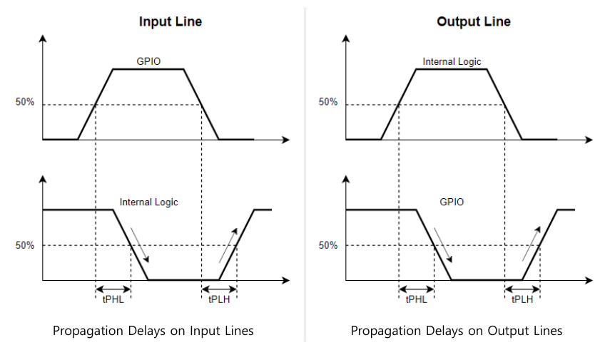
< Figure 30 – Propagation Delay >
Input Line
Output Line
0.533 us
tPHL
0.126 us
0.01 us
tPLH
1.31 us
< Table 10 – Propagation Delay >
*Due to differences in TTL and devices, some errors may occur
Appendix C. Exposure Start / End Delay
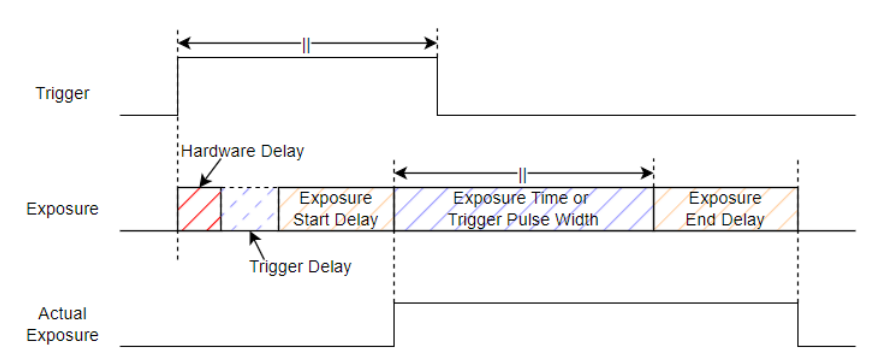
There is a certain delay from the trigger input until the sensor starts actual exposure.
< Figure 31 – Exposure Start & End Delay >
① HC-A130SW
Exposure Start Delay = 13.89us (Min)
Exposure End Delay(Exposure Offset) = 7.372us
*Exposure Start Delay is 2 Line Period based on Sensor Readout, so it may vary depending on settings such as ROI, ADC Bit Depth, Device Tap Geometry, etc.
*Exposure End Delay (=Exposure Offset) is a fixed value as a unique characteristic of the sensor.
*Hardware Delay – Refer to Appendix B
*Trigger Delay can be set in camera feature
Appendix D. User Set Savable & Loadable XML Feature List
The XML Feature List that allows User Set Save / Load is as follows.
Feature
Save / Load
Feature
Save / Load
Device Tap Geometry
O
Gain Selector
X
Width / Height
O
Gain Raw
O
Offset X / Y
O
Gain Abs
O
Binning Horizontal / Vertical Mode
O
Gain Auto
O
Binning Horizontal / Vertical
O
Black Level Selector
X
Decimation Horizontal / Vertical
O
Black Level Raw
O
Reverse X / Y
O
Gamma Enable
O
ADC Bit Depth
O
Gamma
O
Pixel Format
O
LUT Enable
O
Test Pattern
O
LUT Index
O
Trigger Mode
O
LUT Value
O
Trigger Source
O
DefectFilter Enable
O
Trigger Delay
O
Defectfilter Test Mode Selector
X
Line Debounce Time
O
Defect Pixel Replacement Count
O
Fine Shutter Enable
O
Defect Pixel Index
O
Exposure Mode
O
Defect Pixel X Coordinate
O
Exposure Time
O
Defect Pixel Y Coordinate
O
Exposure Auto
O
FFC Enable
O
Auto Exposure Target
O
FFC User Selector
X
Auto Exposure Time Lower / Upper Limit
O
Sharpness Enable
O
Acquisition Frame Rate Enable
O
Sharpness Strength
O
Acquisition Frame Rate
O
Sharpness Filter Size
O
Line Selector
X
Contrast
O
Line Mode
O
Brightness
O
Line Inverter
O
Histogram Stretch Min / Max
O
Line Source
O
Auto Contrast Mode
O
User Output Selector
X
Auto Contrast Factor Low / High
O
User Output Value
O
Auto Contrast Target Low / High
O
Timer Selector
X
Sensor Cooling Auto
O
Timer Duration
O
Sensor Cooling Target
O
Timer Delay
O
Sensor Cooling Voltage
O
Counter Event Source
X
Appendix E. UART Command List
The UART Command List is as follows. Be careful with settings as malfunctions may occur due to incorrect parameter input. (For information related to UART communication, refer to 5. UART communication)
Read Device Temperature 0 : Sensor / 1 : FPGA / 2 : Case
Image Format Control
RHMAX
-
-
Read HMax
RTAPCFG
-
-
Read/Write CL Output Tap
WTAPCFG
1 / 2 / 3
-
RWIDTHMAX
-
-
Read WidthMax
RHEIGHTMAX
-
-
Read HeightMax
RWIDTH
-
-
Read/Write Width Max : WidthMax – Offset X
WWIDTH
64 ~ Max
-
RHEIGHT
-
-
Read/Write Height Max : HeightMax – Offset Y
WHEIGHT
32 ~ Max
-
ROFFSETX
-
-
Read/Write Offset X Max : WidthMax – Width
WOFFSETX
0 ~ Max
-
ROFFSETY
-
-
Read/Write Offset Y Max : HeightMax – Height
WOFFSETY
0 ~ Max
-
RBENMODE
-
-
Read/Write Binning Mode 0x00 : Binning H Average & Binning V Average / 0x01 : Binning H Sum & Binning V Average / 0x10 : Binning H Average & Binning V Sum / 0x11 : Binning H Sum & Binning V Sum
WBENMODE
00 / 01 / 10 / 11
-
RBEN
-
-
Read/Write Binning 0x11 : Normal / 0x12 : Binning H / 0x21 : Binning V / 0x22 : Binning H & V
WBEN
11 / 12 / 21 / 22
-
RSKIP
-
-
Read/Write Decimation 0x11 : Normal / 0x12 : Decimation H / 0x21 : Decimation V / 0x22 : Decimation H & V
WSKIP
11 / 12 / 21 / 22
-
RFLIPMODE
-
-
Read/Write Reverse X, Y 0 : Normal / 1 : Reverse Y / 2 : Reverse X / 3 : Reverse X & Y
Read/Write Exposure Time(us) Min : Minimum Exposure Time
WSHTSET
Min ~ 2DC6C0
-
RAECMODE
-
-
Read/Write Auto Exposure Control Mode 0 : Off / 1 : Once / 2 : Continuous
WAECMODE
0 / 1 / 2
-
RAETARGET
-
-
Read/Write Auto Exposure Target
WAETARGET
0 ~ FF
-
RAEMIN
-
-
Read/Write Auto Exposure Time Lower Limit Max : Auto Exposure Time Upper Limit
WAEMIN
64 ~ Max
-
RAEMAX
-
-
Read/Write Auto Exposure Time Upper Limit Min : Auto Exposure Time Lower Limit
WAEMAX
Min ~ 2DC6C0
-
RFREERUNEN
-
-
Read/Write Acquisition Frame Rate Enable 0 : Off / 1 : On
WFREERUNEN
0 / 1
-
RFREERUN
-
-
Read/Write Frame Period(us) Min : Minimum Frame Period
WFREERUN
Min ~ F4240
-
RMINFREERUN
-
-
Read Minimum Frame Period(us)
REALFREERUN
-
-
Read Real Frame Period(us)
Digital IO Control
RLINEMODE
0 / 1 / 2 / 3 / 4 / 5 / 6
-
Read/Write Line Mode [P1] 0 : Line 1 (CC1) / 1 : Line 2 (CC2) / 2 : Line 3 (CC3) / 3 : Line 4 (GPIO1) / 4 : Line 5 (GPIO2) / 5 : Line 6 (OptoCoupled1) / 6 : Line 7 (OptoCoupled2) [P2] 0 : Input / 1 : Output
WLINEMODE
3 / 4
0 / 1
RLINEINVEN
0 / 1 / 2 / 3 / 4 / 5 / 6
-
Read/Write Line Inverter Enable [P1] 0 : Line 1 (CC1) / 1 : Line 2 (CC2) / 2 : Line 3 (CC3) / 3 : Line 4 (GPIO1) / 4 : Line 5 (GPIO2) / 5 : Line 6 (OptoCoupled1) / 6 : Line 7 (OptoCoupled2) [P2] 0 : Off / 1 : On
WLINEINVEN
0 / 1 / 2 / 3 / 4 / 5 / 6
0 / 1
RLINESTATUS
0 / 1 / 2 / 3 / 4 / 5 / 6
-
Read Line Status 0 : Line 1 (CC1) / 1 : Line 2 (CC2) / 2 : Line 3 (CC3) / 3 : Line 4 (GPIO1) / 4 : Line 5 (GPIO2) / 5 : Line 6 (OptoCoupled1) / 6 : Line 7 (OptoCoupled2)
RLINESRC
3 / 4
-
Read/Write Line Source [P1] 3 : Line 4 (GPIO1) / 4 : Line 5 (GPIO2) [P2] F : Off / 0 : Timer 1 Active / 1 : Exposure Active / 2 : User Output 1 / 3 : User Output 2 / 4 : User Output 3
WLINESRC
3 / 4
F / 0 / 1 / 2 / 3 / 4
RUSEROUTPUT
0 / 1 / 2
-
Read/Write User Output Value [P1] 0 : User Output 1 / 1 : User Output 2 / 2 : User Output 3 [P2] 0 : Low / 1 : High