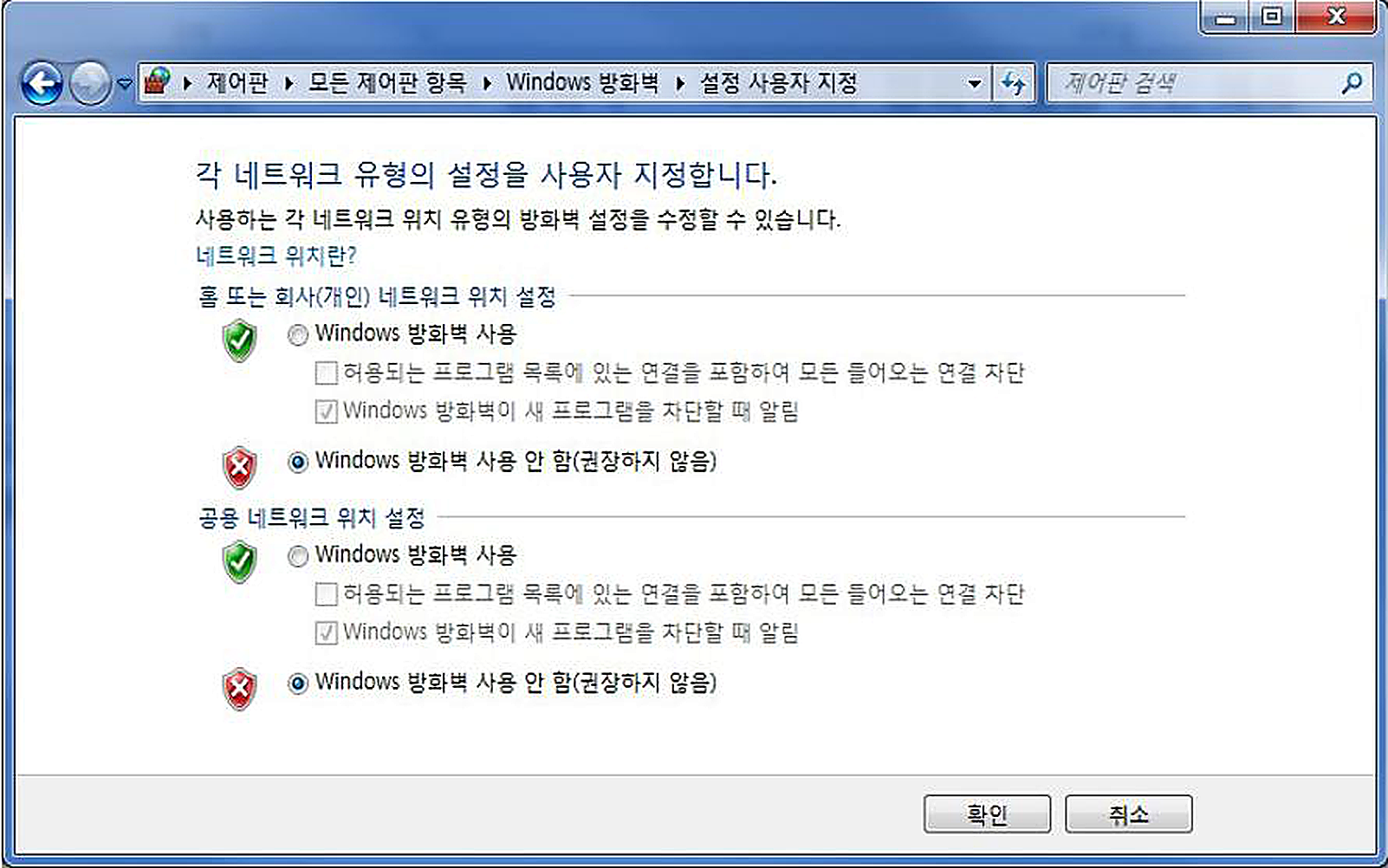
1) Windows 7
시작 ▶ 제어판 ▶ Windows 방화벽 ▶ Windows 방화벽 설정 또는 해제
GigE Vision Camera Manual
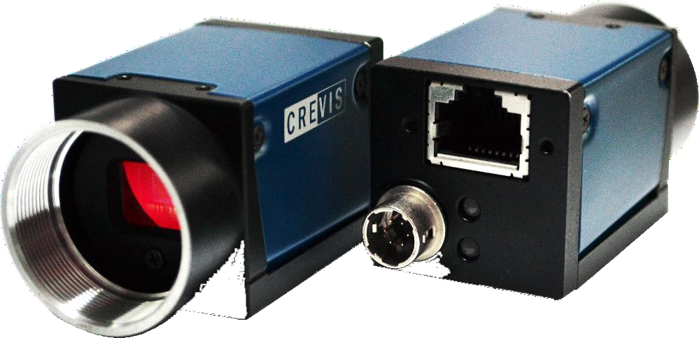
Sony CMOS GigE Camera USER MANUAL

1) CPU : Intel Core i3(최소), i5이상(권장)
2) RAM : 2GB 이상(최소), 8GB 이상(권장)
3) O/S : Windows 7(32bit/64bit) 이상
4) LAN Card : Intel PRO/1000xT 이상
5) VGA : FHD지원(최소), UHD 지원 이상(권장)
1) Windows 7
시작 ▶ 제어판 ▶ Windows 방화벽 ▶ Windows 방화벽 설정 또는 해제
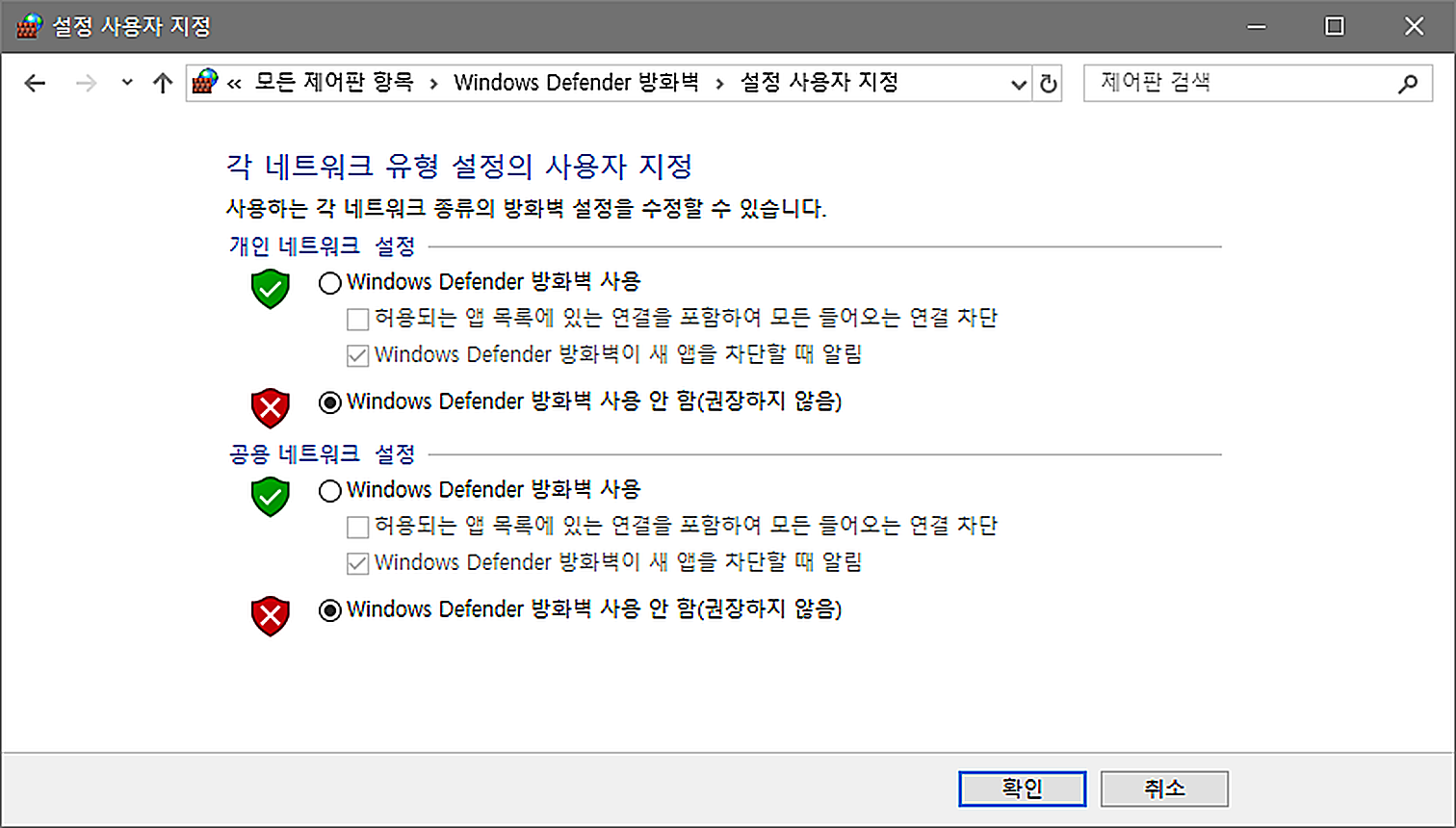
2) Windows 8, 8.1, 10
시작 ▶ 제어판 ▶ Windows Defender 방화벽 ▶ Windows Defender 방화벽 설정 또는 해제
(단, n은 패킷 사이즈가 점보 프레임을 초과하지 않는 범위의 값).
Ex) 2048 * 1024 해상도의 이미지를 전송할 경우의 권장 패킷 사이즈 = (2048 * 8) + 36 = 8228.
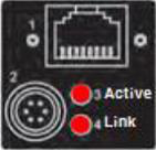
1) 카메라의 현재 상태를 카메라 뒷면의 LED 를 통해 확인이 가능합니다.
2) 호스트와 카메라간의 연결이 제한되거나 영상 취득에 실패할 경우 LED의 상태를 확인하십시오.
상단 : 적색 고정하단 : 적색 고정
이더넷 연결 해제 또는
10Mb 또는 100Mb 접속
상단 : 적색 점등하단 : 녹색 점등
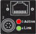
DHCP IP 설정 중
상단 : 꺼짐하단 : 녹색 점등
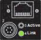
IP 설정 완료 후 대기
(Acquisition Start 대기)
상단 : 녹색 점등/점멸하단 : 녹색 점등
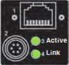
상단 녹색 LED 점멸시 : 이미지 전송중
상단 녹색 LED 점등시 : Trigger 입력 대기
제품 자체에 방수 기능이 없으므로 지나친 습기에 노출되지 않도록 주의하셔야 합니다.
입출력신호가 강한 자기장 및 전기장에 노출되면 신호의 왜곡을 일으킬 수 있으므로 주의하셔야 합니다.
소비전력은 사용환경에 따라 차이가 나지만 전력 소비량이 높으므로 제품 주변을 밀폐시키거나
공기흐름을 차단하지 말고 통풍성을 유지하여야 합니다.
| Spec. | MG-A160M/K-72 | MG-A040M/K-280 | MG-A121M/K-9 | MG-A500M/K-22 | MG-A320M/K-35 | MG-A600R/L-17 | MG-A121R/L-9 | MG-A201R/L-5 | |
|---|---|---|---|---|---|---|---|---|---|
| Sensor | 1.6M | 0.4M | 12.2M | 5M | 3.2M | 6M | 12.1M | 20.1M | |
| Sensor | IMX273LL(Q)R-C | IMX287LL(Q)R-C | IMX304LL(Q)R-C | IMX264LL(Q)R-C | IMX265LL(Q)R-C | IMX178LL(Q)J | IMX226CL(Q)J-C | IMX183CL(Q)J-C | |
| Sensor Format | 1/2.9" | 1/2.9" | 1.1" | 2/3" | 1/1.8" | 1/1.8" | 1/1.7" | 1 | |
| Pixel Size(um) | 3.45 x 3.45 | 6.90 x 6.90 | 3.45 x 3.45 | 3.45 x 3.45 | 3.45 x 3.45 | 2.4 x 2.4 | 1.85 x 1.85 | 2.4 x 2.4 | |
| Active Pixels | 1456 x 1088 | 728 x 544 | 4112 x 3008 | 2464 x 2056 | 2064 x 1544 | 3096 x 2076 | 4024 x 3036 | 5496 x 3672 | |
| Frame Rate (Max)* |
72fps | 280fps | 9ps | 22fps | 35fps | 17fps | 9fps | 5fps | |
| Exposure Time | Min.1us + 14.26us |
Min.1us + 14.26us |
Min.1us + 14.26us |
Min.1 +13.73us |
Min.1 +13.73us |
Min.243.5us | Min.313.5us | Min.430us | |
| Scanning Method |
Full / ROI(Horizontal+Vertical) / Reverse(X,Y,All) | Full / ROI(Horizontal+Vertical) / Reverse(X,Y,All) | Full / ROI(Horizontal+Vertical) / Reverse(X,Y,All) | Full / ROI(Horizontal+Vertical) / Reverse(X,Y,All) | Full / ROI(Horizontal+Vertical) / Reverse(X,Y,All) | Full / ROI(Horizontal+Vertical) / Reverse(X,Y,All) | Full / ROI(Horizontal+Vertical) / Reverse(X,Y,All) | Full / ROI(Horizontal+Vertical) / Reverse(X,Y,All) | |
| Binning | O (Only Mono Model) |
X | X | X | X | X | X | X | |
| ADC Bit Depth | 12bit | 12bit | 12bit | 12bit | 12bit | 12bit | 12bit | 10bit | |
| Sync. System | Internal(Freerun), External(6-pin Circular port), Software trigger via PC | Internal(Freerun), External(6-pin Circular port), Software trigger via PC | Internal(Freerun), External(6-pin Circular port), Software trigger via PC | Internal(Freerun), External(6-pin Circular port), Software trigger via PC | Internal(Freerun), External(6-pin Circular port), Software trigger via PC | Internal(Freerun), External(6-pin Circular port), Software trigger via PC | Internal(Freerun), External(6-pin Circular port), Software trigger via PC | Internal(Freerun), External(6-pin Circular port), Software trigger via PC | |
| Trigger Mode | Timed, Trigger Width | Timed, Trigger Width | Timed, Trigger Width | Timed, Trigger Width | Timed, Trigger Width | Timed, Trigger Width | Timed, Trigger Width | Timed, Trigger Width | |
| Shutter | Global Shutter | Global Shutter | Global Shutter | Global Shutter | Global Shutter | Rolling Shutter | Rolling Shutter / Global Reset | Rolling Shutter / Global Reset | |
| Gain Abs | Analog : 0dB ~ 32dB (1x ~ 39.8x) Digital : 0dB ~ 24dB (1x ~ 16x) |
Analog : 0dB ~ 32dB (1x ~ 39.8x) Digital : 0dB ~ 24dB (1x ~ 16x) |
Analog : 0dB ~ 32dB (1x ~ 39.8x) Digital : 0dB ~ 24dB (1x ~ 16x) |
Analog : 0dB ~ 32dB (1x ~ 39.8x) Digital : 0dB ~ 24dB (1x ~ 16x) |
Analog : 0dB ~ 32dB (1x ~ 39.8x) Digital : 0dB ~ 24dB (1x ~ 16x) |
Analog : 0dB ~ 27dB(1x ~ 22.5x) Digital : 0dB ~ 24dB(1x ~ 16x) |
Analog : 0dB ~ 27dB(1x ~ 22.5x) Digital : 0dB ~ 24dB(1x ~ 16x) |
Analog : 0dB ~ 27dB(1x ~ 22.5x) Digital : 0dB ~ 24dB(1x ~ 16x) |
|
| Black Level (Analog) |
Analog : 0 ~ 4095 (12bit) Digital : 0 ~ 4095 (12bit) |
Analog : 0 ~ 4095 (12bit) Digital : 0 ~ 4095 (12bit) |
Analog : 0 ~ 4095 (12bit) Digital : 0 ~ 4095 (12bit) |
Analog : 0 ~ 4095 (12bit) Digital : 0 ~ 4095 (12bit) |
Analog : 0 ~ 4095 (12bit) Digital : 0 ~ 4095 (12bit) |
Analog : 0 ~ 255 (8bit) Digital : 0 ~ 4095 (12bit) |
Analog : 0 ~ 255 (8bit) Digital : 0 ~ 4095 (12bit) |
Analog : 0 ~ 255 (8bit) Digital : 0 ~ 4095 (12bit) |
|
| LUT | Adjustable LUT (12bit to 12bit) | Adjustable LUT (12bit to 12bit) | Adjustable LUT (12bit to 12bit) | Adjustable LUT (12bit to 12bit) | Adjustable LUT (12bit to 12bit) | Adjustable LUT (12bit to 12bit) | Adjustable LUT (12bit to 12bit) | 10bit to 10bit | |
| Gamma | Gamma Correction(0 ~ 3.999) | Gamma Correction(0 ~ 3.999) | Gamma Correction(0 ~ 3.999) | Gamma Correction(0 ~ 3.999) | Gamma Correction(0 ~ 3.999) | Gamma Correction(0 ~ 3.999) | Gamma Correction(0 ~ 3.999) | Gamma Correction(0 ~ 3.999) | |
| Auto White Balance |
Off / Once / Continuous (Only Color Models) | Off / Once / Continuous (Only Color Models) | Off / Once / Continuous (Only Color Models) | Off / Once / Continuous (Only Color Models) | Off / Once / Continuous (Only Color Models) | Off / Once / Continuous (Only Color Models) | Off / Once / Continuous (Only Color Models) | Off / Once / Continuous (Only Color Models) | |
| Auto Gain/Exposure |
Off / Once / Continuous Auto Exposure(Gain) Lower Limit / Auto Exposure(Gain) Upper Limit |
Off / Once / Continuous Auto Exposure(Gain) Lower Limit / Auto Exposure(Gain) Upper Limit |
Off / Once / Continuous Auto Exposure(Gain) Lower Limit / Auto Exposure(Gain) Upper Limit |
Off / Once / Continuous Auto Exposure(Gain) Lower Limit / Auto Exposure(Gain) Upper Limit |
Off / Once / Continuous Auto Exposure(Gain) Lower Limit / Auto Exposure(Gain) Upper Limit |
Off / Once / Continuous Auto Exposure(Gain) Lower Limit / Auto Exposure(Gain) Upper Limit |
Off / Once / Continuous Auto Exposure(Gain) Lower Limit / Auto Exposure(Gain) Upper Limit |
Off / Once / Continuous Auto Exposure(Gain) Lower Limit / Auto Exposure(Gain) Upper Limit |
|
| ROI | Horizontal / Vertical ROI Support | Horizontal / Vertical ROI Support | Horizontal / Vertical ROI Support | Horizontal / Vertical ROI Support | Horizontal / Vertical ROI Support | Horizontal / Vertical ROI Support | Horizontal / Vertical ROI Support | Horizontal / Vertical ROI Support | |
| Video I/F | Ethernet 1000 Base-T (GigE Vision Standard) | Ethernet 1000 Base-T (GigE Vision Standard) | Ethernet 1000 Base-T (GigE Vision Standard) | Ethernet 1000 Base-T (GigE Vision Standard) | Ethernet 1000 Base-T (GigE Vision Standard) | Ethernet 1000 Base-T (GigE Vision Standard) | Ethernet 1000 Base-T (GigE Vision Standard) | Ethernet 1000 Base-T (GigE Vision Standard) | |
| Video Format | Mono Model : Mono8/10/12, Mono10/12Packed Color Model : Mono8/10/12, Mono10/12Packed, BayerRG8/10/12, BayerRG10/12Packed, YUV422Packed (Not support 12bit mode for MG-A201R/L) |
Mono Model : Mono8/10/12, Mono10/12Packed Color Model : Mono8/10/12, Mono10/12Packed, BayerRG8/10/12, BayerRG10/12Packed, YUV422Packed (Not support 12bit mode for MG-A201R/L) |
Mono Model : Mono8/10/12, Mono10/12Packed Color Model : Mono8/10/12, Mono10/12Packed, BayerRG8/10/12, BayerRG10/12Packed, YUV422Packed (Not support 12bit mode for MG-A201R/L) |
Mono Model : Mono8/10/12, Mono10/12Packed Color Model : Mono8/10/12, Mono10/12Packed, BayerRG8/10/12, BayerRG10/12Packed, YUV422Packed (Not support 12bit mode for MG-A201R/L) |
Mono Model : Mono8/10/12, Mono10/12Packed Color Model : Mono8/10/12, Mono10/12Packed, BayerRG8/10/12, BayerRG10/12Packed, YUV422Packed (Not support 12bit mode for MG-A201R/L) |
Mono Model : Mono8/10/12, Mono10/12Packed Color Model : Mono8/10/12, Mono10/12Packed, BayerRG8/10/12, BayerRG10/12Packed, YUV422Packed (Not support 12bit mode for MG-A201R/L) |
Mono Model : Mono8/10/12, Mono10/12Packed Color Model : Mono8/10/12, Mono10/12Packed, BayerRG8/10/12, BayerRG10/12Packed, YUV422Packed (Not support 12bit mode for MG-A201R/L) |
Mono Model : Mono8/10/12, Mono10/12Packed Color Model : Mono8/10/12, Mono10/12Packed, BayerRG8/10/12, BayerRG10/12Packed, YUV422Packed (Not support 12bit mode for MG-A201R/L) |
|
| Communication | GigE Vision Standard | GigE Vision Standard | GigE Vision Standard | GigE Vision Standard | GigE Vision Standard | GigE Vision Standard | GigE Vision Standard | GigE Vision Standard | |
| Minimum Illumination | 1.0 lx, F1.4, Gain MAX, without IR cut filter | 1.0 lx, F1.4, Gain MAX, without IR cut filter | 1.0 lx, F1.4, Gain MAX, without IR cut filter | 1.0 lx, F1.4, Gain MAX, without IR cut filter | 1.0 lx, F1.4, Gain MAX, without IR cut filter | 1.0 lx, F1.4, Gain MAX, without IR cut filter | 1.0 lx, F1.4, Gain MAX, without IR cut filter | 1.0 lx, F1.4, Gain MAX, without IR cut filter | |
| SNR | B/W : 36dB Color : 36dB |
B/W : 37dB Color : 37dB |
B/W : 42dB Color : 36dB |
B/W : 36dB Color : 36dB |
B/W : 38dB Color : 38dB |
B/W : 40dB Color : 40dB |
B/W : 40dB Color : 40dB |
B/W : 39dB Color : 39dB |
|
| Function Control | GainAuto, ExposureAuto, BalanceWhiteAuto, Acquisition Frame Rate(Adjustable), Gamma Control, Line Debouncer, Color Transformation Control, Noise Reduction Filter, Pattern Noise Removal |
GainAuto, ExposureAuto, BalanceWhiteAuto, Acquisition Frame Rate(Adjustable), Gamma Control, Line Debouncer, Color Transformation Control, Noise Reduction Filter, Pattern Noise Removal |
GainAuto, ExposureAuto, BalanceWhiteAuto, Acquisition Frame Rate(Adjustable), Gamma Control, Line Debouncer, Color Transformation Control, Noise Reduction Filter, Pattern Noise Removal |
GainAuto, ExposureAuto, BalanceWhiteAuto, Acquisition Frame Rate(Adjustable), Gamma Control, Line Debouncer, Color Transformation Control, Noise Reduction Filter, Pattern Noise Removal |
GainAuto, ExposureAuto, BalanceWhiteAuto, Acquisition Frame Rate(Adjustable), Gamma Control, Line Debouncer, Color Transformation Control, Noise Reduction Filter, Pattern Noise Removal |
GainAuto, ExposureAuto, BalanceWhiteAuto, Acquisition Frame Rate(Adjustable), Gamma Control, Line Debouncer, Color Transformation Control, Noise Reduction Filter, Pattern Noise Removal |
GainAuto, ExposureAuto, BalanceWhiteAuto, Acquisition Frame Rate(Adjustable), Gamma Control, Line Debouncer, Color Transformation Control, Noise Reduction Filter, Pattern Noise Removal |
GainAuto, ExposureAuto, BalanceWhiteAuto, Acquisition Frame Rate(Adjustable), Gamma Control, Line Debouncer, Color Transformation Control, Noise Reduction Filter, Pattern Noise Removal |
|
| Lens mount | C mount | C mount | C mount | C mount | C mount | C mount | C mount | C mount | |
| Power Supply | DC(12V ± 10%) or PoE | DC(12V ± 10%) or PoE | DC(12V ± 10%) or PoE | DC(12V ± 10%) or PoE | DC(12V ± 10%) or PoE | DC(12V ± 10%) or PoE | DC(12V ± 10%) or PoE | DC(12V ± 10%) or PoE | |
| Consum- ption |
DC | < 3.1W | < 3.1W | < 3.2W | < 3W | < 3.2W | < 3.0W | < 3W | < 3.2W |
| Consum- ption |
POE | < 3.6W | < 3.6W | < 3.7W | < 3.5W | < 3.7W | < 3.5W | < 3.5W | < 3.7W |
| Weight | < 60g | < 60g | < 60g | < 60g | < 60g | < 60g | < 60g | < 60g | |
| Dimension | 29 x 29 x 40 mm (Without mount, Connector) | 29 x 29 x 40 mm (Without mount, Connector) | 29 x 29 x 40 mm (Without mount, Connector) | 29 x 29 x 40 mm (Without mount, Connector) | 29 x 29 x 40 mm (Without mount, Connector) | 29 x 29 x 40 mm (Without mount, Connector) | 29 x 29 x 40 mm (Without mount, Connector) | 29 x 29 x 40 mm (Without mount, Connector) | |
| Operating / Storage |
0℃ ~ +45℃ (with < 20~80% RH) /-20℃ ~ +60℃ | 0℃ ~ +45℃ (with < 20~80% RH) /-20℃ ~ +60℃ | 0℃ ~ +45℃ (with < 20~80% RH) /-20℃ ~ +60℃ | 0℃ ~ +45℃ (with < 20~80% RH) /-20℃ ~ +60℃ | 0℃ ~ +45℃ (with < 20~80% RH) /-20℃ ~ +60℃ | 0℃ ~ +45℃ (with < 20~80% RH) /-20℃ ~ +60℃ | 0℃ ~ +45℃ (with < 20~80% RH) /-20℃ ~ +60℃ | 0℃ ~ +45℃ (with < 20~80% RH) /-20℃ ~ +60℃ | |
| Vibration / Shock |
10G / 20G | 10G / 20G | 10G / 20G | 10G / 20G | 10G / 20G | 10G / 20G | 10G / 20G | 10G / 20G | |
| Standard Compliancy |
CE (EN61326-1; 2006년; Class A) | CE (EN61326-1; 2006년; Class A) | CE (EN61326-1; 2006년; Class A) | CE (EN61326-1; 2006년; Class A) | CE (EN61326-1; 2006년; Class A) | CE (EN61326-1; 2006년; Class A) | CE (EN61326-1; 2006년; Class A) | CE (EN61326-1; 2006년; Class A) | |
| Environments | RoHS / WEEE | RoHS / WEEE | RoHS / WEEE | RoHS / WEEE | RoHS / WEEE | RoHS / WEEE | RoHS / WEEE | RoHS / WEEE |
| Spec. | Spec. | MG-A500M/K-FL | MG-A500M/K-FL | MG-A121M/K-FL | MG-A121M/K-FL | MG-A161M/K-FL | MG-A161M/K-FL | MG-A241M/K-FL |
|---|---|---|---|---|---|---|---|---|
| Sensor | Sensor | 5M | 5M | 12M | 12M | 16M | 16M | 24M |
| Sensor | Sensor | IMX547-AAM(Q)J-C | IMX547-AAM(Q)J-C | IMX545-AAM(Q)J-C | IMX545-AAM(Q)J-C | IMX542-AAM(Q)J-C | IMX542-AAM(Q)J-C | IMX540-AAM(Q)J-C |
| Sensor Size | Sensor Size | 1/1.8" | 1/1.8" | 1/1.1" | 1/1.1" | 1.1" | 1.1" | 1.2" |
| Pixel Size(um) | Pixel Size(um) | 2.74 x 2.74 | 2.74 x 2.74 | 2.74 x 2.74 | 2.74 x 2.74 | 2.74 x 2.74 | 2.74 x 2.74 | 2.74 x 2.74 |
| Resolution (Effective Size) |
Resolution (Effective Size) |
2472 x 2064 | 2472 x 2064 | 4128 x 3008 | 4128 x 3008 | 5328 x 3040 | 5328 x 3040 | 5328 x 4608 |
| Resolution (Effective Size) |
Resolution (Effective Size) |
2472 x 2064 | 2472 x 2064 | 4128 x 3008 | 4128 x 3008 | 5328 x 3040 | 5328 x 3040 | 5328 x 4608 |
| Pixel Clock | Pixel Clock | 74.219MHz | 74.219MHz | 74.219MHz | 74.219MHz | 74.219MHz | 74.219MHz | 74.219MHz |
| Frame Rate (max.) | Frame Rate (max.) | 22fps | 22fps | 9fps | 9fps | 7fps | 7fps | 4fps |
| Frame Rate (max.) | Frame Rate (max.) | (actual 22.08 fps) | (actual 22.08 fps) | (actual 9.07 fps) | (actual 9.07 fps) | (actual 7.03 fps) | (actual 7.03 fps) | (actual 4.64 fps) |
| Scanning Method | Scanning Method | Full / AOI / Reverse(X,Y,All) | Full / AOI / Reverse(X,Y,All) | Full / AOI / Reverse(X,Y,All) | Full / AOI / Reverse(X,Y,All) | Full / AOI / Reverse(X,Y,All) | Full / AOI / Reverse(X,Y,All) | Full / AOI / Reverse(X,Y,All) |
| Scanning Method | Scanning Method | / Decimation (Horizontal+Vertical ) | / Decimation (Horizontal+Vertical ) | / Decimation (Horizontal+Vertical ) | / Decimation (Horizontal+Vertical ) | / Decimation (Horizontal+Vertical ) | / Decimation (Horizontal+Vertical ) | / Decimation (Horizontal+Vertical ) |
| Scanning Method | Scanning Method | / Binning (Horizontal+Vertical) (Only Mono Models) | / Binning (Horizontal+Vertical) (Only Mono Models) | / Binning (Horizontal+Vertical) (Only Mono Models) | / Binning (Horizontal+Vertical) (Only Mono Models) | / Binning (Horizontal+Vertical) (Only Mono Models) | / Binning (Horizontal+Vertical) (Only Mono Models) | / Binning (Horizontal+Vertical) (Only Mono Models) |
| Synchronization | Synchronization | Internal(Freerun), External, Software trigger via PC | Internal(Freerun), External, Software trigger via PC | Internal(Freerun), External, Software trigger via PC | Internal(Freerun), External, Software trigger via PC | Internal(Freerun), External, Software trigger via PC | Internal(Freerun), External, Software trigger via PC | Internal(Freerun), External, Software trigger via PC |
| Trigger Mode | Trigger Mode | Fixed shutter, Pulse width shutter | Fixed shutter, Pulse width shutter | Fixed shutter, Pulse width shutter | Fixed shutter, Pulse width shutter | Fixed shutter, Pulse width shutter | Fixed shutter, Pulse width shutter | Fixed shutter, Pulse width shutter |
| GPIO | GPIO | PhotoCoupler Input 1ch, Output 1ch | PhotoCoupler Input 1ch, Output 1ch | PhotoCoupler Input 1ch, Output 1ch | PhotoCoupler Input 1ch, Output 1ch | PhotoCoupler Input 1ch, Output 1ch | PhotoCoupler Input 1ch, Output 1ch | PhotoCoupler Input 1ch, Output 1ch |
| Shutter | Shutter | Global shutter | Global shutter | Global shutter | Global shutter | Global shutter | Global shutter | Global shutter |
| Shutter Speed | Shutter Speed | 1us ~ 3sec | 1us ~ 3sec | 1us ~ 3sec | 1us ~ 3sec | 1us ~ 3sec | 1us ~ 3sec | 1us ~ 3sec |
| Shutter Speed | Shutter Speed | (Exposure Offset : 2.47 us) | (Exposure Offset : 2.47 us) | (Exposure Offset : 2.47 us) | (Exposure Offset : 2.46 us) | (Exposure Offset : 2.46 us) | (Exposure Offset : 2.46 us) | (Exposure Offset : 2.46 us) |
| Gain | Gain | Analog : 0dB ~ 24 dB (1x ~ 15.8x), Digital : 0dB ~ 24 dB (1x ~ 16x) |
Analog : 0dB ~ 24 dB (1x ~ 15.8x), Digital : 0dB ~ 24 dB (1x ~ 16x) |
Analog : 0dB ~ 24 dB (1x ~ 15.8x), Digital : 0dB ~ 24 dB (1x ~ 16x) |
Analog : 0dB ~ 24 dB (1x ~ 15.8x), Digital : 0dB ~ 24 dB (1x ~ 16x) |
Analog : 0dB ~ 24 dB (1x ~ 15.8x), Digital : 0dB ~ 24 dB (1x ~ 16x) |
Analog : 0dB ~ 24 dB (1x ~ 15.8x), Digital : 0dB ~ 24 dB (1x ~ 16x) |
Analog : 0dB ~ 24 dB (1x ~ 15.8x), Digital : 0dB ~ 24 dB (1x ~ 16x) |
| Black Level | Black Level | Analog : 0 ~ 4095 (12bit), Digital : 0 ~ 4095 (12bit) |
Analog : 0 ~ 4095 (12bit), Digital : 0 ~ 4095 (12bit) |
Analog : 0 ~ 4095 (12bit), Digital : 0 ~ 4095 (12bit) |
Analog : 0 ~ 4095 (12bit), Digital : 0 ~ 4095 (12bit) |
Analog : 0 ~ 4095 (12bit), Digital : 0 ~ 4095 (12bit) |
Analog : 0 ~ 4095 (12bit), Digital : 0 ~ 4095 (12bit) |
Analog : 0 ~ 4095 (12bit), Digital : 0 ~ 4095 (12bit) |
| Gamma / LUT | Gamma / LUT | Gamma Correction(0 ~ 3.999), Adjustable LUT (12bit to 12bit) | Gamma Correction(0 ~ 3.999), Adjustable LUT (12bit to 12bit) | Gamma Correction(0 ~ 3.999), Adjustable LUT (12bit to 12bit) | Gamma Correction(0 ~ 3.999), Adjustable LUT (12bit to 12bit) | Gamma Correction(0 ~ 3.999), Adjustable LUT (12bit to 12bit) | Gamma Correction(0 ~ 3.999), Adjustable LUT (12bit to 12bit) | Gamma Correction(0 ~ 3.999), Adjustable LUT (12bit to 12bit) |
| Interface | Interface | Ethernet 1000 Base-T(GigE Vision Standard) | Ethernet 1000 Base-T(GigE Vision Standard) | Ethernet 1000 Base-T(GigE Vision Standard) | Ethernet 1000 Base-T(GigE Vision Standard) | Ethernet 1000 Base-T(GigE Vision Standard) | Ethernet 1000 Base-T(GigE Vision Standard) | Ethernet 1000 Base-T(GigE Vision Standard) |
| Pixel Data Format | Pixel Data Format | Mono Model : Mono8/10/12, Mono10/12Packed | Mono Model : Mono8/10/12, Mono10/12Packed | Mono Model : Mono8/10/12, Mono10/12Packed | Mono Model : Mono8/10/12, Mono10/12Packed | Mono Model : Mono8/10/12, Mono10/12Packed | Mono Model : Mono8/10/12, Mono10/12Packed | Mono Model : Mono8/10/12, Mono10/12Packed |
| Pixel Data Format | Pixel Data Format | Color Model : Mono8/10/12, Mono10/12Packed, BayerRG8/10/12, BayerRG10/12Packed,YUV422Packed | Color Model : Mono8/10/12, Mono10/12Packed, BayerRG8/10/12, BayerRG10/12Packed,YUV422Packed | Color Model : Mono8/10/12, Mono10/12Packed, BayerRG8/10/12, BayerRG10/12Packed,YUV422Packed | Color Model : Mono8/10/12, Mono10/12Packed, BayerRG8/10/12, BayerRG10/12Packed,YUV422Packed | Color Model : Mono8/10/12, Mono10/12Packed, BayerRG8/10/12, BayerRG10/12Packed,YUV422Packed | Color Model : Mono8/10/12, Mono10/12Packed, BayerRG8/10/12, BayerRG10/12Packed,YUV422Packed | Color Model : Mono8/10/12, Mono10/12Packed, BayerRG8/10/12, BayerRG10/12Packed,YUV422Packed |
| SNR | SNR | B/W : 38dB | B/W : 39dB | B/W : 39dB | B/W : 38dB | B/W : 38dB | B/W : 38dB | B/W : 38dB |
| SNR | SNR | Color : 39dB | Color : 40dB | Color : 40dB | Color : 38dB | Color : 38dB | Color : 39dB | Color : 39dB |
| Function Control | Function Control | GainAuto, ExposureAuto, BalanceWhiteAuto(Only Color Models) | GainAuto, ExposureAuto, BalanceWhiteAuto(Only Color Models) | GainAuto, ExposureAuto, BalanceWhiteAuto(Only Color Models) | GainAuto, ExposureAuto, BalanceWhiteAuto(Only Color Models) | GainAuto, ExposureAuto, BalanceWhiteAuto(Only Color Models) | GainAuto, ExposureAuto, BalanceWhiteAuto(Only Color Models) | GainAuto, ExposureAuto, BalanceWhiteAuto(Only Color Models) |
| Function Control | Function Control | Acquisition Frame Rate(Adjustable), Line Debouncer | Acquisition Frame Rate(Adjustable), Line Debouncer | Acquisition Frame Rate(Adjustable), Line Debouncer | Acquisition Frame Rate(Adjustable), Line Debouncer | Acquisition Frame Rate(Adjustable), Line Debouncer | Acquisition Frame Rate(Adjustable), Line Debouncer | Acquisition Frame Rate(Adjustable), Line Debouncer |
| Function Control | Function Control | Color Transformation Control, Noise Reduction Filter | Color Transformation Control, Noise Reduction Filter | Color Transformation Control, Noise Reduction Filter | Color Transformation Control, Noise Reduction Filter | Color Transformation Control, Noise Reduction Filter | Color Transformation Control, Noise Reduction Filter | Color Transformation Control, Noise Reduction Filter |
| Lens mount | Lens mount | C mount | C mount | C mount | C mount | C mount | C mount | C mount |
| Power Requirements | Power Requirements | 12VDC ± 10% or PoE | 12VDC ± 10% or PoE | 12VDC ± 10% or PoE | 12VDC ± 10% or PoE | 12VDC ± 10% or PoE | 12VDC ± 10% or PoE | 12VDC ± 10% or PoE |
| Consumption | DC12V | < 3.1W | < 3.3W | < 3.3W | < 3.6W | < 3.6W | < 3.8W | < 3.8W |
| Consumption | PoE | < 3.6W | < 3.8W | < 3.8W | < 4.2W | < 4.2W | < 4.3W | < 4.3W |
| Weight | Weight | < 65g | < 65g | < 65g | < 65g | < 65g | < 65g | < 65g |
| Dimensions | Dimensions | 29 x 29 x 40 mm (Without mount) | 29 x 29 x 40 mm (Without mount) | 29 x 29 x 40 mm (Without mount) | 29 x 29 x 40 mm (Without mount) | 29 x 29 x 40 mm (Without mount) | 29 x 29 x 40 mm (Without mount) | 29 x 29 x 40 mm (Without mount) |
| Temperature (Operating / Storage) |
Temperature (Operating / Storage) |
0℃ ~ +40℃ / -10℃ ~ +50℃ (with < 20~80% RH) | 0℃ ~ +40℃ / -10℃ ~ +50℃ (with < 20~80% RH) | 0℃ ~ +40℃ / -10℃ ~ +50℃ (with < 20~80% RH) | 0℃ ~ +40℃ / -10℃ ~ +50℃ (with < 20~80% RH) | 0℃ ~ +40℃ / -10℃ ~ +50℃ (with < 20~80% RH) | 0℃ ~ +40℃ / -10℃ ~ +50℃ (with < 20~80% RH) | 0℃ ~ +40℃ / -10℃ ~ +50℃ (with < 20~80% RH) |
| Vibration / Shock | Vibration / Shock | 98 m/s2 (10.0 G) / 196 m/s2 (20.0 G) | 98 m/s2 (10.0 G) / 196 m/s2 (20.0 G) | 98 m/s2 (10.0 G) / 196 m/s2 (20.0 G) | 98 m/s2 (10.0 G) / 196 m/s2 (20.0 G) | 98 m/s2 (10.0 G) / 196 m/s2 (20.0 G) | 98 m/s2 (10.0 G) / 196 m/s2 (20.0 G) | 98 m/s2 (10.0 G) / 196 m/s2 (20.0 G) |
| Standard Compliancy | Standard Compliancy | CE (EN61326-1; 2006년; Class A) | CE (EN61326-1; 2006년; Class A) | CE (EN61326-1; 2006년; Class A) | CE (EN61326-1; 2006년; Class A) | CE (EN61326-1; 2006년; Class A) | CE (EN61326-1; 2006년; Class A) | CE (EN61326-1; 2006년; Class A) |
| Conformity | Conformity | RoHS / WEEE | RoHS / WEEE | RoHS / WEEE | RoHS / WEEE | RoHS / WEEE | RoHS / WEEE | RoHS / WEEE |
| NO. | Name | Remark |
|---|---|---|
| 1 | Gigabit Ethernet 커넥터 | RJ45 |
| 2 | 전원 & 외부 I/O 커넥터 | 6Pin Circular |
| 3, 4 | LED 상태표시 | LED |
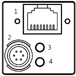
1) 6 pin Circular Connector
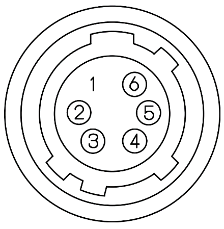
| No. | Name | IN/OUT | Description | Remark |
|---|---|---|---|---|
| 1 | DC VCC | IN | 10.8V ~ 13.2V Input Range | |
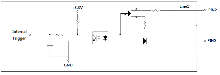
| 2 | TRIGGER+ | IN | Opto-isolated Trigger input (+2.5V~24V) |
|
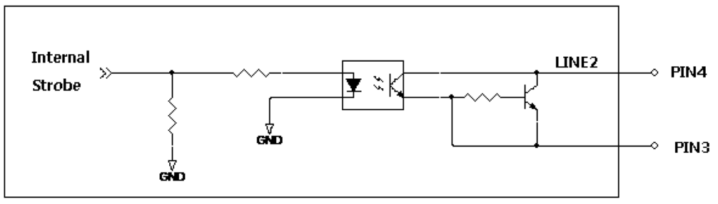
| 3 | STROBE- | OUT | ||
| 4 | STROBE+ | OUT | Opto-isolated Strobe output (+3.3V) |
|
| 5 | TRIGGER- | IN | ||
| 6 | DC GND | IN |
1) Direct & Cross cable 지원
2) PoE 지원(IEEE 802.3af)
3) Cat5e UTP cable 지원, 보다 나은 안정성을 위해서 Cat6. STP cable 권장
| LED(하단) | Status | LED(상단) | Status |
|---|---|---|---|
| Off | 전원 꺼짐 | Off | 대기상태 |
| Red | 10Mb/100Mb Link | Red | IP 할당, IP 설정 오류 |
| Green | Gigabit Link | Green | 점등시 (Trigger 입력 대기) 점멸시 (이미지 전송) |
Input
Output
카메라의 이미지 출력 Size 및 Format에 대한 설정을 변경할 수 있는 기능 입니다.
| Item | Setting Value | Description |
|---|---|---|
| Width, Height, Offset X, Offset Y |
(Integer) | 이미지의 출력 Size 및 Offset(Pixel 좌표)를 변경합니다. WidthMAX ≥ Offset X + Width HeightMAX ≥ Offset Y + Height |
| Decimation Horizontal, Decimation Vertical |
1, 2 | 이미지의 해상도가 낮아지며, Frame Rate은 증가합니다. |
| Binning Horizontal Binning Vertical |
1,2 | 이미지의 해상도가 낮아지며, 감도는 증가합니다. (단, MG-A160M-72 모델에 한함) |
| ReverseX, ReverseY |
True / False | 이미지의 상/하 또는 좌/우 반전됩니다. |
| Pixel Format | Mono8/Bayer8 Mono10/Bayer10 Mono12/Bayer12 Packed10, 12 YUV422Packed |
이미지를 Host로 전송할 때의 Format을 변경할 수 있습니다. 세부적인 전송 Order은 4.1.4절을 참고해 주시기 바랍니다. |
| Test Pattern | Off, Vertical Ramp, Horizontal Ramp |
테스트 이미지를 선택할 수 있습니다. |
Width, Height, Offset X, Offset Y 를 설정함으로써 원하는 영역의 이미지만 출력하는 것이 가능합니다.
출력 이미지 사이즈가 작아질수록 Frame Rate 이 증가합니다.
(단, MG-A121R(L)-9 모델은 Frame Rate 이 증가하지 않습니다.)
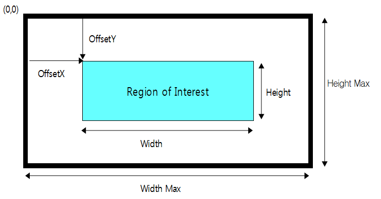
참고사항 : ROI 로 인해 변경된 Frame Rate 은 'Resulting Frame Rate' 파라미터를 통해 확인할 수 있습니다.
이미지 센서에서 수직 또는 수평 방향으로 1-Pixel 씩 건너뛰며 읽어내는 기능입니다. 이미지의 해상도는 절반으로 줄어드는 반면 Frame Rate 는 증가합니다. Color 모델의 경우, 네 개의 컬러 채널을 모두 표현하기 위해 2-Pixel 단위로 건너뛰게 됩니다.
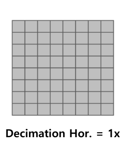
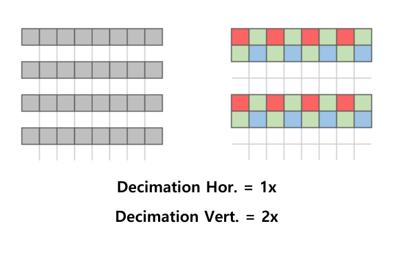
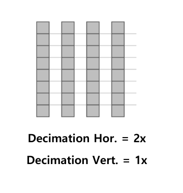
참고사항 : Decimation 으로 인해 변경된 Frame Rate 은 'Resulting Frame Rate' 파라미터를 통해 확인할 수 있습니다.
이미지 센서에서 수직 또는 수평 방향으로 인접한 픽셀끼리 누적한 다음 차례로 읽어내는 기능입니다.
Decimation 과 동일한 해상도를 갖는 반면, Binning 은 영상 신호가 더해지기 때문에 감도 또한 약 두배 가량 상승하게 됩니다.
참고사항 : Binning 으로 인해 변경된 Frame Rate 은 'Resulting Frame Rate' 파라미터를 통해 확인할 수 있습니다.
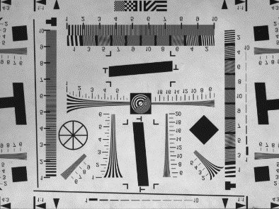
영상의 좌/우 또는 상/하를 반전하여 출력하는 기능입니다. Color 모델의 경우 'Reverse Mode' 따라 'Bayer Pixel Order'도 함께 바뀐 상태로 이미지가 출력 됩니다.
1) Reverse X 모드를 True 로 설정시, 영상의 좌/우가 반전됩니다. (Bayer RG → Bayer GR)
2) Reverse Y 모드를 True 로 설정시, 영상의 상/하가 반전됩니다. (Bayer RG → Bayer GB)
유의사항
1) 'Reverse Y' 선택 시 Defect Filter 사용이 제한되기 때문에 불량 화소가 나타날 수 있습니다. 이로 인해 노출된 불량화소는 'Defect Pixel Correction' 카테고리에서 제거할 수 있습니다. ('Defect Pixel Correction'절 참고)
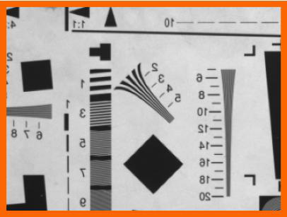
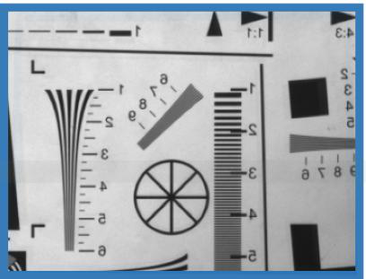
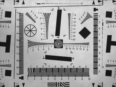
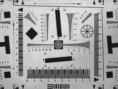
2) ROI 와 Reverse 가 동시에 사용될 경우, 반전된 이미지로부터 ROI 기능이 적용됩니다. 아래 그림과 같이 Reverse 가 활성화 될 경우 Image 의 시작 좌표인 (0,0) Pixel 의 위치가 반전됩니다. 이 때문에 Reverse 적용 이전과 동일한 영역을 촬상하기 위해선 Total Size - ROI Size 만큼의 Image Offset 이 필요합니다.
영상의 Pixel Format 을 변경할 수 있는 기능입니다. 각 Pixel Format 별 이미지 데이터의 전송량에 차이가 있기 때문에 전송 속도 및 Bandwidth 가 달라질 수 있습니다.
8-bit image data into 8bits
Description : 8-bit monochrome unsigned
Pixel Size : 1byte
Pixel Value range : 0 to 255

10-bit image data into 16-bits
Description : 10-bit monochrome
Pixel Size : 2byte
Pixel Value range : 0 to 1023

12-bit image data into 16-bits
Description : 12-bit monochrome unsigned
Pixel Size : 2byte
Pixel Value range : 0 to 4095

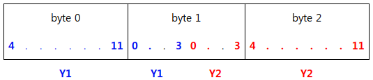
2 X 10-bit image data packed into 24bits (Y1, Y2)
Description : 10-bit packed monochrome unsigned
Pixel Size : 3 bytes for two pixels
Pixel Value range : 0 to 1023
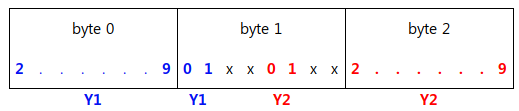
2 X 12-bit image data packed into 24bits (Y1, Y2)
Description : 12-bit packed monochrome unsigned
Pixel Size : 3 bytes for two pixels
Pixel Value range : 0 to 4095
16-bit image data into 16-bits
Description : 16-bit color unsigned
Pixel Size : 2byte
Pixel Value range : 0 to 255
Y = 0.299*R + 0.587*G + 0.114*B
Cb = 0.492*(B-Y)
Cr = 0.877*(R-Y)

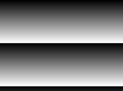
이미지 프로세싱의 중간 단계에서 영상을 테스트 패턴으로 치환하여 전송합니다. Test Pattern 기능이 활성화 되더라도 ROI size 및 Trigger 입력 그리고 'Acquisition Frame Rate'등 이미지 취득과 관련된 기능들은 유효합니다. Test Pattern 이미지는 8bit grey level(0~255DN)로 생성 됩니다.

카메라에서 이미지를 획득하는 방식을 설정할 수 있는 기능입니다. 획득할 이미지 프레임 수를 정의할 수 있습니다.
| Item | Setting Value | Description |
|---|---|---|
| Acquisition Mode | Continuous, Single Frame, Multi Frame |
Acquisition Start 커맨드로 부터 아래 조건 까지 영상을 취득합니다. - Continuous : Acquisition Stop 까지 연속으로 취득합니다. - Single Frame : 한 장의 이미지만을 취득합니다. - Multi Frame : 설정한 카운트 만큼만 영상을 취득합니다. |
| Acquisition Start | Excute | 영상 획득 시작 Command |
| Acquisition Stop | Excute | 영상 획득 종료 Command |
| Acquisition Frame Count | 0 to 255 | Acquisition Start 시점부터 Burst 로 전송할 이미지의 수. 'Acquisition Mode'가 'Multi Frame' 일 때에만 설정값이 유효합니다. |
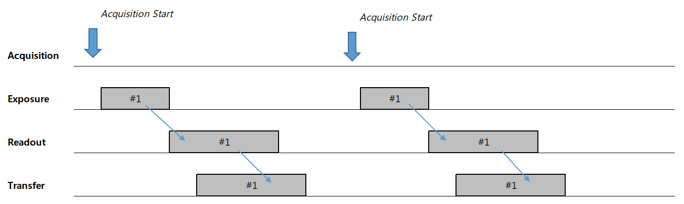
'Acquisition Start' 커맨드가 입력될 때 마다 한 장의 이미지를 촬상하고 전송합니다. 한 장의 이미지만 전송한 뒤 자동으로 Acquisition 을 멈추기 때문에 별도의 'Acquisition Stop' 커맨드는 필요하지 않습니다. 만일 'Trigger Mode' 가 'On' 일 경우에는 트리거에 의해 노광이 되고 전송 됩니다. Trigger Mode 가 'Off' 일 경우에는 'Acquisition Start' 커맨드 만으로 새로운 이미지 획득 및 전송이 가능합니다.
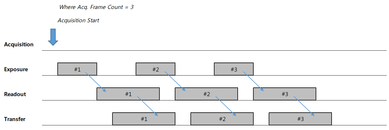
'Acquisition Start' 커맨드가 입력될 때마다 'Acquisition Frame Count'에 정의된 수 만큼 이미지를 촬상하고 전송합니다. 지정된 카운트 만큼 이미지를 전송한 뒤 자동으로 Acquisition 이 멈추기 때문에 별도의 'Acquisition Stop' 커맨드는 필요하지 않습니다. 하지만 Grab 도중 'Acquisition Stop' 커맨드가 입력될 경우, 노광중인 프레임 까지 Readout 및 전송한 뒤 멈춥니다. 만일 'Trigger Mode'가 'On' 일 경우에는 입력 트리거에 의해 노광이 되고 전송 됩니다.
'Acquisition Start' 커맨드가 입력된 시점으로 부터 'Acquisition Frame Rate'에 정의된 주기로 이미지를 촬상하고 전송합니다. Grab 중 'Acquisition Stop' 커맨드가 입력될 경우, 현재 노출중인 이미지 까지는 Readout 하고 전송한 뒤 Acquisition 을 멈추게 됩니다. 노광이 종료된 시점에 'Acquisition Stop' 커맨드가 입력되면 진행중이던 Readout 까지 마친 뒤에 Acquisition 이 종료 됩니다. 만일 'Trigger Mode' 가 'On' 일 경우에는 트리거에 의해 노광이 되고 전송됩니다.
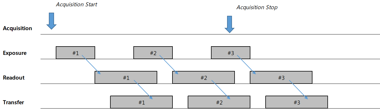
이미지 획득 및 출력 타이밍을 제어합니다. 영상 획득 방법으로는 크게 외부 동기(Trigger Mode = On)와 내부 동기(Trigger Mode = Off, Freerun Mode) 모드가 있으며 취득 지연 또는 전송 지연 등을 설정할 수 있습니다.
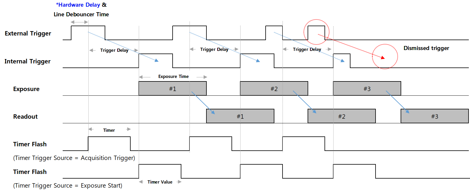
* Minimum Trigger width : 35us
* Hardware Delay
| Rising edge | Falling edge | |
|---|---|---|
| Opto-isolated Input | 4.5 us | 35 us |
| Item | Setting Value | Description |
|---|---|---|
| Trigger Mode | Off, On | Off : 카메라가 Freerun모드로 동작합니다. Internal Trigger 신호가 생성됩니다. Internal Trigger의 주기는 'Acquisition Frame Rate'에 의해 결정됩니다. 만약 'Acquisition Frame Rate Enable' 파라미터가 Off일 경우, 카메라는 현재 카메라 세팅에서 동작할 수 있는 최대 Frame rate로 동작합니다. On : 카메라가 Trigger Mode로 동작합니다. Trigger는 하드웨어 (Line 1) 또는 소프트웨어 트리거 커맨드를 통해 생성됩니다. |
| Resulting Frame Rate | (Read Only) | Trigger Mode가 Off로 설정된 상태에서의 Frame Rate를 보여줍니다. 이미지 사이즈와 'Acquisition Frame Rate', 'Exposure Time' 및 'Pixel Format', 'Decimation' 등에 의해 결정됩니다. |
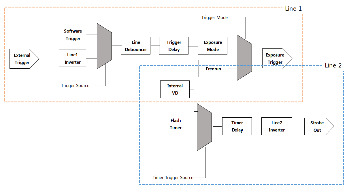
| Trigger Sourece | Line1, Software | Trigger 입력으로 사용하고자 하는 Trigger의 Source를 선택합니다. 세부사항은 아래 Trigger Source 항목을 참조하세요. |
| Trigger Delay | 0 to 57,844,677 (Unit : us) |
카메라가 입력받은 트리거로 부터 이미지 센서의 노광까지의 지연 시간을 정의합니다. 세팅 값 0은 Delay Off를 의미 합니다. 세부사항은 아래 Trigger Delay 항목을 참조하세요. |
| Transfer Delay | 0 to 57,844,677 (Unit : Clock) |
센서로부터 읽어온 이미지를 전송 최종단에서 지연시킬 시간을 정의합니다. 'Low Latency Mode Enable'이 'False' 일 때에만 유효합니다. 세부사항은 아래 Transfer Delay 항목을 참조하세요. |
| Trigger Activation | Rising Edge (Read Only) |
카메라 내부의 Trigger 신호 위상의 기준을 정의합니다. 입력 트리거의 위상을 변경하기 위해선 'Line Inverter'를 사용합니다. |
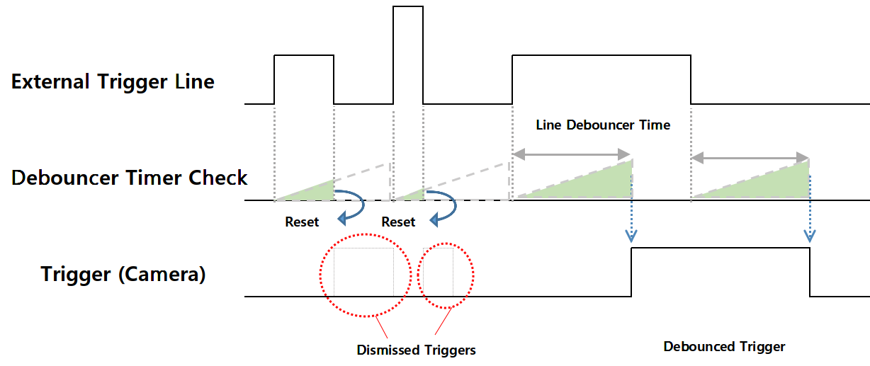
| Line debouncer Time | 0 to 882.995 (Unit : us) |
Line Debouncer Time을 조정합니다. 세부사항은 아래 Line Debouncer 항목을 참조하세요. |
'Trigger Mode'는 이미지 센서의 노광을 제어하는 기능입니다.
'Trigger Mode'를 'Off'로 설정할 경우, 카메라는 Freerun Mode로 동작합니다. Freerun mode는 현재 설정 상태로 동작할 수 있는 최대 Frame Rate으로 Internal VD가 생성 됩니다. 이와 동시에 설정된 'Exposure Time' 만큼 노광 신호가 생성되어 이미지 센서로 입력됩니다. 생성된 Exposure 신호에 의해 주기적인 노광이 이뤄지며 그에 따라 노출된 이미지를 읽어온 뒤 Host로 전송합니다.
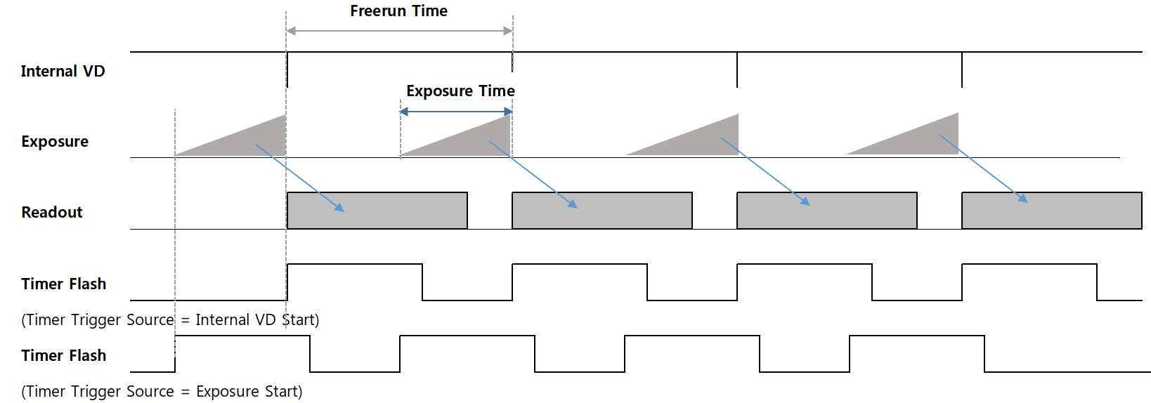
반면 Trigger Mode를 'On'으로 설정할 경우, 카메라는 Trigger Mode로 동작하게 됩니다. Trigger mode는 외부로부터 입력받은 Trigger에 의해 노광 시작 시점 또는 노광 시간 등이 결정 됩니다. 노광이 완료된 후 부터는 Freerun mode와 동일하게 프레임을 읽어오고 전송합니다. 자세한 타이밍은 p.22<Timing Diagram of Trigger Signals> 그림을 참고해 주시기 바랍니다.
유의사항
1) 제품의 최대 Frame Rate보다 빠른 주기의 Trigger 신호가 입력될 경우, 출력 이미지의 Sync는
손상됩니다. (비정상 트리거 입력 판별은 'Counter Control' 참조) 따라서 카메라 사양 이내의 신호 규격을 준수하여 입력해 주시기 바랍니다.
2) 트리거 신호 Line에 노이즈가 유입될 경우, 카메라가 노이즈를 트리거 신호로 오인할 가능성이 있습니다. (노이즈 필터링 관련 'Line Debouncer Time' 기능 참조)
트리거 신호의 Source를 정의합니다. Trigger Mode가 On으로 설정되어 있을 때 적용됩니다.
Line1 : 2번 핀(Trigger +)과 5번 핀(Trigger -)을 통해 트리거를 입력 받습니다. 트리거의 전압 레벨 범위는 최소2.5V에서 최대 24V까지 입니다.
Software 함수를 통해 카메라 내부에 트리거를 생성합니다. 이 설정에서는 'Exposure Mode'가 'Timed'셔터 모드로만 지원됩니다.
참고사항
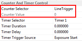
'Counter And Timer Control' 카테고리의 'Counter Selector'를 'Line Trigger' 로 설정하면 카메라로
입력한 총 유효 트리거 수가 'Counter Value'로 리턴 됩니다. 이 카운터는 'Acquisition Start' 커맨드에 의해 0으로 초기화 됩니다.
트리거 입력 시점으로 부터 'Trigger Delay'에 설정된 값 만큼 카메라 내부에서 트리거가 지연되어 동작하도록 설정하는 기능입니다. 만일 'Trigger Delay'가 0이 아닌 값이 설정되어 트리거 신호가 지연되는 도중 새로운 트리거 신호가 입력될 경우, 기존의 트리거 신호에 대한 지연은 지속 되며 새로운 트리거는 무시 됩니다. 즉, 트리거의 주기보다 지연시간이 더 클 경우, Trigger 누락에 의해 Frame Rate이 저하될 수 있습니다. 자세한 타이밍도는 P.22<Timing Diagram of Trigger Signals> 도해를 참고해 주시기 바랍니다.
카메라 내부에서 이미지 전처리(Pre-processing)까지 마친 영상을 전송하는 단계에서 이미지 Packet의 전송 시작 시점을 지연시키는 기능 입니다. 다수의 카메라 영상을 단일 Host에서 입력받는 경우 입력 타이밍을 조정하여 입력 시점을 분산할 수 있습니다.
파라미터의 입력 값은 Clock 단위 이므로, 시간으로 환산하기 위해 아래 식을 참조 하십시오.
유의사항
1) 'Low-latency Mode Enable' 파라미터가 'False'로 설정된 경우에 한해 설정 가능합니다.
2) 보다 자세한 타이밍은 '4.15.1 Low-Latency Mode' 를 참고해 주시기 바랍니다.
카메라의 노광 방식을 선택하는 기능입니다. 'Trigger Source'가 'Line1'으로 설정되어 있을 경우, 'Timed' 및 'Trigger Width'로 각각 설정이 가능합니다. 'Trigger Source'가 'Software'로 설정된 경우에는 'Timed' 셔터로만 동작합니다.
'Timed' 셔터 방식은 'Exposure Time'에 설정된 시간 만큼만 노광이 이루어지게 됩니다. 트리거는 단지 노광의 시작 시점을 지정하는 역할을 합니다. 반면 'Trigger Width' 셔터 방식은 트리거 신호의 Pulse 폭이 유효한 노광 시간이 됩니다.
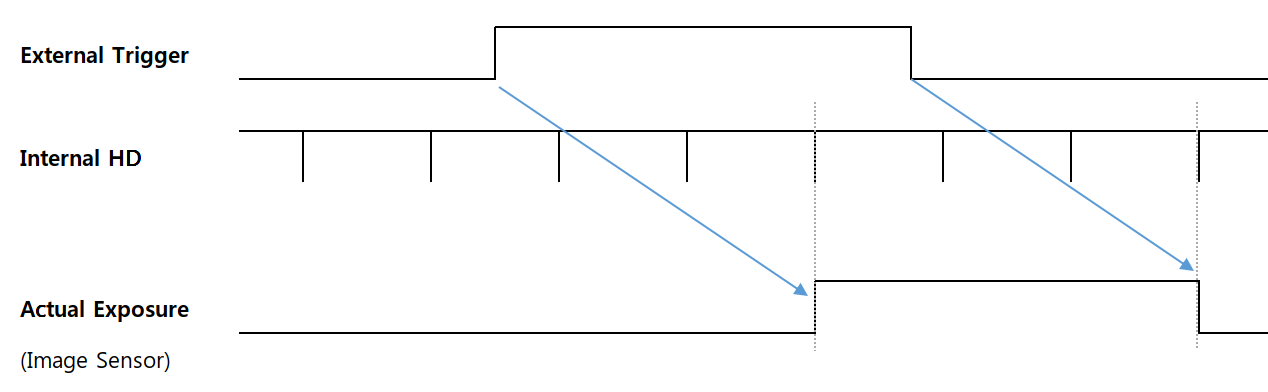
유의사항
'Trigger Width' 모드의 실제 노광 시간은 카메라 내부의 'HD'신호에 의해 래치되기 때문에 3HD의 지연이 발생합니다.
카메라의 노광시간을 설정합니다. 이 시간은 'Exposure Mode'가 'Timed'로 설정되어 있는 경우에만 적용됩니다. Freerun Mode에서는 'Exposure Time'이 Frame 주기 보다 길어질 경우, Frame Rate이 감소하게 됩니다.
카메라 내부의 실제 노광 신호는 'HD' 타이머에 의해 발생하게 됩니다. 이 'HD' 타이머는 수평 방향의 Readout Size와 관련이 있기 때문에, 일반적으로 Image Width가 작을 수록 HD 신호의 주기도 함께 단축 됩니다. 또한 영상 전송 Bandwidth와 관련된 파라미터(ex. Pixel Format, Device Througput 등)를 변경할 경우에도 HD 신호의 주기가 변경 됩니다.
참고사항
'Counter And Timer Control' 카테고리의 'Counter Selector'를 'Exposure Start' 또는 'Exposure End' 로 설정하면 카메라에서 노광의 시작, 종료 카운트가 'Counter Value'로 리턴 됩니다. 이 카운터는 'Acquisition Start' 커맨드에 의해 0으로 초기화 됩니다.
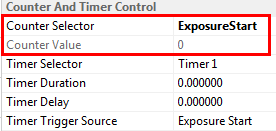
유의사항
1) 이 카메라는 Exposure Time과 실제 노광 시간 사이에 오차가 존재합니다. 아래 표에 명기된 시간은 절대적인 시간으로써, 매 프레임마다 노광할 때 추가되는 Exposure Error(Offset) Time 입니다.
| Model | MG-A160M/K-72 | MG-A040M/K-280 | MG-A121M/K-9 | MG-A500M/K-22 | MG-A320M/K-35 |
|---|---|---|---|---|---|
| Exposure Time Offset | 14.26us | 14.26us | 14.26us | 13.73us | 13.73us |
2) 트리거 신호가 카메라에 도달한 시점 으로부터 노광 시작(및 노광 종료) 시점이 지연될 수 있습니다. (Hardware 지연 및 'Line Debouncer Time' 제외)
| Delay Type | Delay Time |
|---|---|
| Exposure Start Delay | 3HD |
| Exposure End Delay | 3HD+Exposure Time Offset |
※카메라 F/W Version이 3.4.2.5 이후일 경우에 해당함. 보다 이전 버전의 경우, Exposure Start Delay는 최소 2HD ~ 최대 3HD임.
| Model | MG-A040M/K-280 | MG-A160M/K-72 | MG-A320M/K-35 | MG-A500M/K-22 | MG-A121M/K-9 |
|---|---|---|---|---|---|
| 1HD | 6.1us | 12.33us | 18.31us | 21.91us | 35.69us |
※ 상기 1HD 시간은 최대 Image Size 조건에서 최대 Frame Rate을 출력할 경우를 기준으로 함.
Rolling Shutter 기반 이미지 센서를 채택한 두 제품군에 한해 'Sensor Shutter Mode'를 변경할 수 있습니다. 기본적으로 'Rolling' 모드를 지원 하지만, 피사체가 빠르게 움직일 경우 시간 차에 의한 이미지 왜곡이 나타날 수 있습니다. 반면 Overlap이 가능하기 때문에 제품의 최대 Frame Rate에 도달할 수 있습니다. 모든 Line이 균일한 노광시간을 갖는 장점이 있습니다.
이미지 각 라인을 동시에 Reset 하는 'Global Reset' 모드를 사용하면 시간차에 의한 이미지 왜곡은 사라집니다. 하지만 Reset 직후부터 모든 라인은 노광 상태가 되기 때문에, 수직 방향으로 읽어나갈 수록 노광 시간이 길어지게 됩니다. 때문에 동일한 'Exposure Time'을 설정해도 'Rolling' 모드에 비해 상대적으로 밝은 이미지가 취득 됩니다. 그리고 Overlapping 트리거가 지원되지 않기 때문에 Frame Rate은 약 절반 이하로 감소할 수 있습니다.
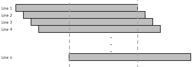
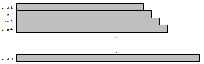
유의사항
'Rolling' 모드에서의 적절한 Exposure Flash 타이밍은 첫 번째 라인과 마지막 라인이 공통적으로 노광하는 사이 시간 입니다. 이 때에만 전체 이미지 라인에 균일한 조명이 조사될 수 있습니다.
'Exposure Time'을 카메라가 자동으로 조정하여 원하는 밝기를 일정하게 유지해 주는 기능입니다. 'ExposureMode'가 'Timed'로 설정되어 있을 때 설정할 수 있습니다. 그리고 'Auto Exposure Time Lower Limit'과 'Auto Exposure Time Upper Limit'의 사이 시간에서만 'Exposure Time'이 변경 됩니다.
| 파라미터 | 설정값 | 설명 |
|---|---|---|
| Exposure Auto | Off Once continuous |
Off : Exposure time을 수동으로 설정합니다. Once : 한번만 노광시간을 조절하여 원하는 밝기 값으로 변경합니다. Continuous : 지속적으로 노광시간을 조절하여 원하는 밝기 값을 유지합니다. |
| Auto Exposure Target | 0 to 255 (8-bit DN) |
사용자가 원하는 밝기값 설정 |
| Auto Exposure Time Lower Limit | Unit : us | 가변 셔터 범위의 최소 값 |
| Auto Exposure Time Upper Limit | Unit : us | 가변 셔터 범위의 최대 값 |
유의사항
1) Exposure Time이 너무 짧을 경우 조명 깜빡임에 의해 깜빡이는 영상이 출력될 수 있습니다.
2) 최대 밝기에 도달하기 위해 'Exposure Time'이 Frame 주기 보다 길어질 경우 Frame Rate가 감소할 수 있습니다.
카메라 외부 I/O 신호를 설정할 수 있는 기능입니다. 각 I/O의 입/출력 방향은 고정되어 있으며, I/O 포트를 통한 신호의 논리적 사양을 변경할 수 있습니다.
| Item | Setting Value | Description |
|---|---|---|
| Line selector | Line1, Line2 | 세부 설정을 원하는 Line을 선택합니다. |
| Line Mode | Input, Output | Line 1은 카메라의 Input Line으로 할당 되어 있습니다. Line 2은 카메라의 Output Line으로 할당 되어 있습니다. |
| Line Inverter | True / False | True : Line의 입/출력 위상을 반전 시킵니다. False : Line의 위상을 반전시키지 않습니다. |
| Line Status | True / False | 선택된 Line의 현재 상태를 반환합니다. True는 Logical High를 의미하며, False는 Logical Low를 의미 합니다. |
| Line Source | Exposure Active, Timer Active, User Output1 |
'Line Selector'가 'Line2'(Output Direction)로 설정된 경우에만 사용가능합니다. Exposure Active : 노광시간 동안 활성화되는 Flash Signal이 출력 됩니다. Timer Active : 'Counter And Timer Control' 카테고리의 'TimerDuration'에 설정된 시간만큼 Flash Signal이 출력 됩니다. User Output1 : 'User Output Value' 값이 출력 됩니다. |
| User Output Value | True / False | 'Line Source'가 User Output1으로 설정되었을 때의 출력 값을 설정합니다. |
카메라 외부 Trigger Line의 채터링 노이즈를 제거(Debouncing)하는 기능입니다. 'Line Debouncer Time'에 설정된 시간 만큼 상태를 유지하는 신호에 대해서만 유효한 입력으로 받습니다. Line Debouncer Timer는 Trigger Line의 상태 변이를 체크하기 때문에 'Line Debouncer Timer'에 설정된 시간만큼 지연된 트리거를 입력받게 됩니다.
Timer Control에서는 카메라 외부로 출력하는 스트로브 신호의 설정을 변경할 수 있습니다. 'Trigger Mode'가 Off일 때 (Freerun Mode)에는 Timer Flash 신호의 생성 시점을 노광 시작 또는 'Internal VD Start' 시점으로 선택할 수 있습니다. (<Timing Diagram of Freerun Mode> 도해 참고) VD가 초기화 되는 시점은 Shutter가 동작하는 시점보다 앞서기 때문에 조명과의 동기를 맞추기 위해 'Timer Delay'가 필요할 수 있습니다.
반면 'Trigger Mode'가 On 일 때에는 노광 시작 시점 또는 Trigger 신호 감지시점(상태변이 시점)을 Timer Flash 생성 위치로 선택할 수 있습니다. 외부 트리거에 의해 Timer가 생성될 경우, 'Timer Delay'를 통해 실제 노광 구간과 동기를 맞출 수 있습니다. (<Timing Diagram of Trigger Signals> 도해 참고)
| Item | Setting Value | Description |
|---|---|---|
| Timer Duration | 0 to 57,844,677 (Unit : us) |
Line2로 출력하는 Timer Flash 신호의 Pulse Width를 정의합니다. 설정값 0은 Off를 의미합니다. |
| Timer Delay | 0 to 57,844,677 (Unit : us) |
Line2로 출력하는 Timer Flash 신호의 발생 지연시간을 정의합니다. 설정값 0은 지연 없음을 의미합니다. |
| Timer Trigger Source | Exposure Start, Acquisition Trigger, Internal VD Start |
Flash Timer가 발생하기 시작하는 시점을 선택합니다. Exposure Start : 노광이 시작되는 시점 Acquisition Trigger : 외부 트리거의 입력 시점 Internal VD Start : Freerun 모드에서의 Internal VD 리셋 시점 |
카메라가 트리거를 입력 받고, 노광하며 이미지를 전송하는 일련의 과정을 단계별 카운터로 모니터링 할 수 있는 기능입니다. 또한 Frame 주기보다 빠른 속도의 트리거 입력 등 카메라 사양을 초과하는 신호 입력에 대한 확인도 가능합니다.
| Item | Setting Value | Description |
|---|---|---|
| Counter Selector | LineTrigger Exposure Start Exposure End FrameEnd ExposureOver- Trigger ReadOutOver- Trigger |
외부로부터 입력되는 Trigger 신호에 대한 카메라 동작 신뢰성을 확인하기 위한 기능입니다. LineTrigger : 총 입력된 Line1 Trigger 및 Software Trigger 개수. Exposure Start : 실제 노광이 시작된 횟수. Exposure End : 실제 노광이 종료된 횟수. FrameEnd : Sensor로부터 Readout한 Frame의 수. ExposureOverTrigger : Exposure 도중 새로운 Trigger가 입력된 개수. ReadOutOverTrigger : Readout 도중 새로운 Exposure가 끝난 횟수. 단, Readout Overtrigger는 Trigger Mask Enable = On 일 때만 카운트 됨. |
| Counter Value | (Read Only) | Acquisition Start 시점에 모든 카운터 값들은 0으로 초기화 됩니다. |
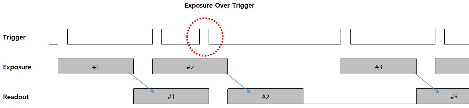
1) Exposure Mode = Timed 일 경우
2) #3 Trigger 신호는 #2 Trigger 신호의 노출 중에 입력되었기 때문에 무시 됩니다.
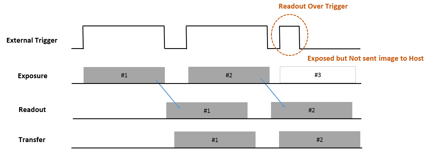
1) Exposure Mode = Trigger Width 일 경우
2) #3 Trigger 신호는 최소 주기보다 빠르게 입력 되었습니다. 따라서 종전에 전송 중인 #2는 방해 없이 전송을 지속하며, Over trigger 입력된 #3의 영상은 전송하지 않습니다. (F/W 3.4.2.5 이상에 한함)
참고사항
Cam Guide SDK에서는 온전하게 수신된 이미지 Packet에 한해 영상을 display 합니다. 필요에 따라 'Device Option Control' 카테고리 중 'Device Missing Packet Display' 옵션을 'On'으로 변경하여 Over-trigger로 인한 이미지 깨짐 현상을 확인할 수 있습니다.
Event 알림은 카메라에서 특정 Event 상황 마다 Host로 Event Packet을 전송하는 기능 입니다. 이미지 전송채널과는 상이한 채널로 Event Packet을 전송하기 때문에 이미지 패킷과 동시 전송이 가능합니다.
| Item | Setting Value | Description |
|---|---|---|
| Event Selector | Exposure End, Acquisition Transfer Start, Acquisition Transfer End, Over Trigger |
Exposure End : 노광이 종료된 시점에 Event를 발생 시킵니다. Acquisition Transfer Start : 이미지 Frame의 전송 시작 시점에 Event를 발생 시킵니다. Acquisition Transfer End : 이미지 Frame의 전송 종료 시점에 Event를 발생 시킵니다. Over Trigger : Exposure 도중에 유입된 Trigger 신호 감지 시점에 Event를 발생 시킵니다. |
| Event Notification | Off, On | 각 Selector의 Event에 대해 알림을 활성화 또는 비활성화 합니다. |
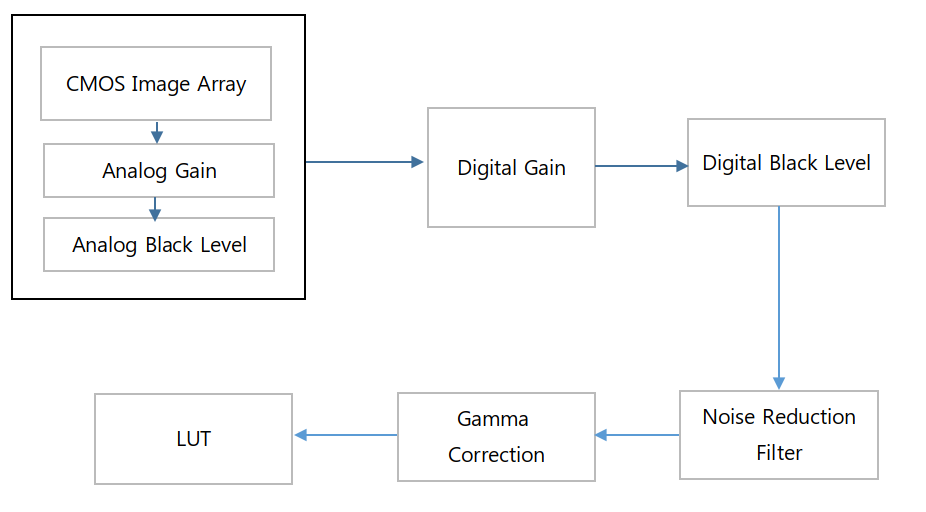
영상 신호의 Analog 및 Digital 특성을 변경할 수 있습니다. 주로 이미지 화소에 대한 속성을 변경할 수 있는 기능이 나열 되어 있습니다.
| <Block Diagram of Analog Control> |
|---|
| Item | Setting Value | Description |
|---|---|---|
| Gain Selector | All, DigitalAll | 설정할 Gain 을 선택합니다. 두 개의 각 Gain은 서로 독립적인 Gain 으로써, 동시에 다른 값을 설정할 수 있습니다. - All : Analog Gain - Digital All : Digital Gain |
| Gain Raw | All : Analog Gain - Global Shutter : 0 to 320 - Rolling Model : 0 to 1957 DigitalAll : Digital Gain (공통) 65536 to 1048575 |
원하는 Gain값을 Raw 값으로 적용할 수 있습니다. |
| Gain Abs | All : Analog Gain - Global Shutter : 1 to 39.8x - Rolling Model : 1 to 22.5x DigitalAll : Digital Gain (공통) 1 to 16x |
원하는 Gain값을 배율로 적용할 수 있습니다. 원본 이미지의 밝기를 1 배로 규정하여 상대적인 배율을 입력할 수 있습니다. ※ 참고 : dB 환산식 Gain_dB = 20 * log(GainAbs) |
| Gain Auto | Off, Once, Continuous | AGC(Automatic gain control) 기능을 설정할 수 있습니다. 이 때 Target 밝기 값은 'Auto Exposure Target'에 정의 됩니다. Off : Gain 을 수동으로 설정합니다. Once : 한번만 Gain값을 조절하여 원하는 밝기 값으로 변경합니다. Continuous : 지속적으로 Gain값을 조절하여 원하는 밝기값을 유지합니다. |
| Auto Gain Lower Limit | Unit : dB | 가변 Gain 범위의 최소 값 |
| Auto Gain Upper Limit | Unit : dB | 가변 Gain 범위의 최대 값 |
| Black Level Selector |
All, DigitalAll | 설정할 Black Level 을 선택합니다. 두 개의 각 BlackLevel은 서로 독립적인 Offset 으로써, 동시에 다른 값을 설정할 수 있습니다. - All : Analog Offset - Digital All : Digital Offset |
| Black Level Raw |
All : Analog Offset -Global Shutter : 0 to 4095 -Rolling Model : 0 to 255 DigitalAll : Digital Offset (공통) 0 to 4095 |
Analog / Digital Black Level 값을 변경 합니다. 이미지 신호의 DC Offset을 조정할 수 있습니다. |
| Pattern Noise Removal | Execute | 패턴 형태의 노이즈를 제거 합니다. (MG-A121R/L-9 및 MG-A201R/L-5 모델에 한함) |
| Noise Reduction Filter | False, True | Noise Reduction 기능을 활성화 합니다. Sharpness가 다소 감소할 수 있습니다. |
Gain은 Frame Rate의 저하 없이 영상의 감도를 변경할 수 있는 반면, 이미지 노이즈 또한 함께 증가할 수 있습니다. 카메라의 Gain은 Analog Gain 및 Digital Gain으로 각각 구성되어 있으며, 'Gain Selector'를 통해 선택할 수 있습니다.
유의사항
'Gain Auto'를 'Exposure Auto' 기능과 일시에 사용할 경우 밝기 변화에 대한 우선 순위
'Black Level'은 카메라의 감도 Offset을 설정할 수 있는 기능입니다 'Black Level'은 Gain과 마찬가지로 Analog Black Level과 Digital Black Level로 구성되어 있으며, 'Black Level Selector'를 통해 선택할 수 있습니다.
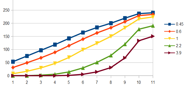
Gamma Correction을 조정하기 위한 기능입니다. 카메라 영상의 명암 대비를 보정할 수 있습니다.
유의사항
MG-A121R/L-9 모델 및 MG-A201R/L-5 모델의 이미지에 모자이크 패턴과 유사한 노이즈가 나타날 수 있습니다. 사용자의 환경(조명, 렌즈 등)에 대한 set-up이 완료된 이후 모자이크 패턴 또는 특정 컬러 채널간의 감도 불균형 현상이 나타날 경우 자체 보정할 수 있는 기능입니다. 'Pattern Noise Removal' 커맨드를 통해 즉시 보정이 가능합니다.
유의사항
1) 'Pattern Noise Removal'을 수행하기 위해 이미지를 Grab 해야 합니다.
2) 커맨드 입력을 통해 영상을 보정한 뒤, 'Userset Save' 커맨드를 통해 카메라에 보정 값을 저장해야 합니다.
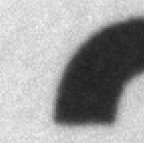
노이즈 필터를 통해 영상 노이즈를 감쇄할 수 있는 기능입니다. 활성화시 다음 Frame부터 반영되며 영상의 Sharpness가 다소 저하될 수 있습니다.

컬러 카메라의 색 균형을 보정하기 위한 기능입니다. 광원에 대한 컬러 채널간 감도 균형을 이루기 위해 보정 합니다. 광원의 색온도가 달라질 경우 새로 보정을 해야 합니다.
| Item | Setting Value | Description |
|---|---|---|
| Balance Ratio Selector |
Red, Green, Blue | Color Gain을 조정하기 위한 색상을 선택합니다. |
| Balance Ratio | 0 to 7.9 | 선택한 색상의 Gain값을 조정합니다. 단위는 배율 입니다. (기본값 : 1x) |
| Balance White Auto |
Off, once, Continuous |
Once : 1 회에 한해 컬러 Gain을 조정하여 화이트 밸런스를 맞춰줍니다. Continuous : 지속적으로 컬러 Gain을 조정하여 화이트 밸런스를 유지하여 줍니다. |
유의사항
1) 특정한 밝기 범위를 벗어난 Pixel은 노이즈로 판단합니다. 또한 특정 Color에 심하게 치우친 경우에도 Auto White Balance 연산에서 제외 됩니다. 자세한 조건은 아래 기준을 참고하십시오.
1. |R-Y| < 160DN
2. |B-Y| < 160DN
3. -160DN < (B-Y) + (R-Y) < 160DN
2) 색 보정 이후 'Userset Save' Command를 통해 보정값을 카메라의 PROM에 저장해야 합니다.
사용자가 설정한 파라미터의 값을 저장 또는 불러오기 위한 기능입니다.
| Item | Setting value | Description |
|---|---|---|
| User Set Selector | Default Userset1 Userset2 Userset3 |
Default : 카메라에 기본으로 저장되어 있는 설정값입니다. 사용자가 저장할 수 없습니다. Userset1/2/3 : 사용자가 임의로 저장/로드가 가능합니다. 전원 Off/On 시에도 저장한 설정으로 유지됩니다. |
| User Set Load | Execute | 선택된 Usersetselector 항목의 설정을 불러옵니다. |
| User Set Save | Execute | 선택된 Usersetselector 항목에 설정을 저장합니다. |
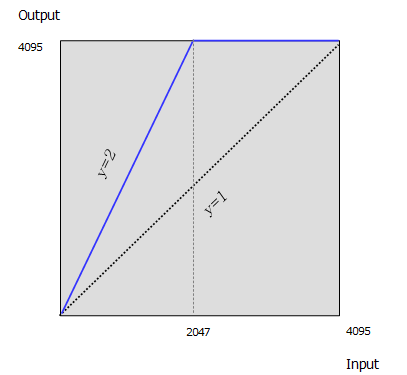
LUT(Look Up Table) 기능은 Digital 변환 된 Pixel 값을 테이블에 입력값 대비 출력값으로 1:1매칭시켜 변환하는 기능 입니다. Table의 각 Index(Input Image)에 정의한 LUT Value(Output Image)로 Pixel 값이 치환 됩니다. 컬러 모델의 경우, 휘도 성분(Luminance)을 LUT메모리에 적재 합니다.
| Item | Setting value | Description |
|---|---|---|
| LUT Enable | Disable, Enable | LUT 기능 활성화 여부를 결정합니다. |
| LUT Index | MG-A201R(L)-5 모델 : 0 to 1023 그 외 모델 : 0 to 4095 |
LUT의 Index값을 조정합니다. Table의 입력 Pixel값 입니다. |
| LUT Value | MG-A201R(L)-5 모델 : 0 to 1023 그 외 모델 : 0 to 4095 |
해당되는 LUT Index의 값을 조정합니다. Table의 출력 Pixel 값 입니다. |
Ex) y=2x 형태로 값을 table을 사용할 경우 저조도 Pixel은 감도 향상 효과를 볼 수 있는 반면, 고조도 Pixel은 포화 상태가 되므로 Dynamic Range에 손실이 발생함.
| Index | 0 | 1 | 2 | 3 | 4 | 5 | … | 1024 | … | 2047 | 2048 | 2049 |
|---|---|---|---|---|---|---|---|---|---|---|---|---|
| Value | 0 | 2 | 4 | 6 | 8 | 0xA | … | 0X800 | … | 0xFFE | 0xFFF | 0xFFF |
유의사항
카메라의 Defect Pixel을 관리할 수 있는 기능입니다. 출하시 불량 화소에 대한 보정이 이루어 집니다. 하지만 사용자가 불량 화소라고 생각하는 Pixel을 추가로 정의하여 보정할 수 있습니다. 각 카메라당 최대 256개의 불량 화소를 PROM에 저장할 수 있습니다.
| Item | Setting Value | Description |
|---|---|---|
| Defect Filter Enable | False, True | Defect Pixel 보정 여부를 선택 합니다. |
| Defect Filter Test Mode Select | Off, Mark White, Mark Black, Mark White with Black Background | 보정된 Defect Pixel을 영상에 나타내는 옵션 입니다. |
| Defect Pixel Replacement Count |
1 to 256 | 카메라당 보정할 불량화소의 개수 입니다. |
| Defect Pixel Index | 0 to 255 | 보정 할 Defect Pixel의 Index 입니다. |
| Defect Pixel X Coordinate | 0 to WidthMax - 1 | 보정 할 Pixel의 X축 좌표 값을 입력합니다. 이미지 Pixel의 좌표는 0 부터 시작합니다. |
| Defect Pixel Y Coordinate | 0 to HeightMax - 1 | 보정 할 Pixel의 Y축 좌표 값을 입력합니다. 이미지 Pixel의 좌표는 0부터 시작합니다. |
| Defect Pixel X Replacement |
Excute | 입력한 보정 값을 카메라에 적용 합니다. |
유의사항
Ex) 공장 출하시 20개의 Defect Pixel이 보정된 상태에서, 사용자가 두 개의 Pixel을 추가 정의할 경우
| Defect Pixel Replacement Count | Defect Pixel Index | X Coordinate | Y Coordinate |
|---|---|---|---|
| 19 | 18 | … | … |
| 20 | 19 | … | … |
| 21 | 20 | (156, 31) | (1131, 125) |
| 22 | 21 | (208, 114) | (321, 611) |
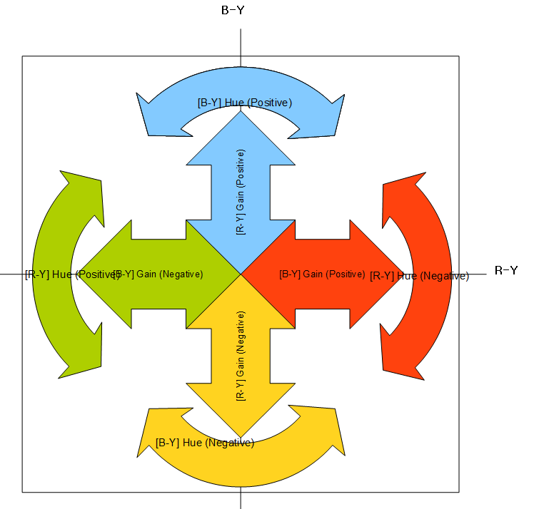
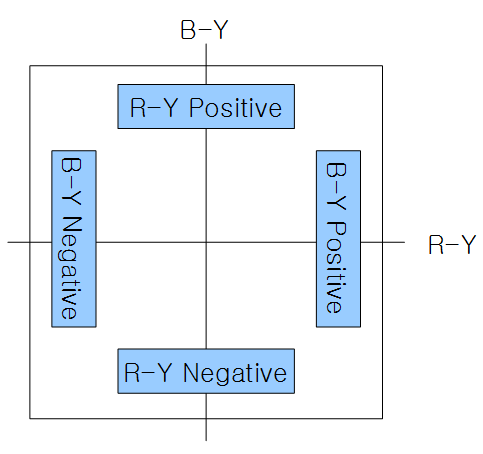
Color Transfermation은 Color Vector 변환을 지원하는 기능 입니다. 이 변환은 B-Y / R-Y 색 공간에서 이루어 집니다. 색조(HUE) 값이 양수이면 Color Vector에서 시계 방향으로의 회전을 의미합니다. 반면 색조(HUE) 값이 음수일 경우에는 반시계 방향으로의 회전을 의미합니다.
| Item | Setting Value | Description |
|---|---|---|
| Color Transformation Enable | True / False | Color Transfermation 기능을 활성화 합니다. 'Pixel Format'이 'YUV422Packed'로 설정된 경우에만 유효 합니다. |
| Color Trasformation Value Selector |
[B-Y] Gain (Positive) : B-Y Positive의 Color Gain [B-Y] Gain (Negative) : B-Y Negative의 Color Gain [R-Y] Gain (Positive) : R-Y Positive의 Color Gain [R-Y] Gain (Negative) : R-Y Negative의 Color Gain [B-Y] Hue (Positive) : B-Y Positive의 Color hue(rotation) [B-Y] Hue (Negative) : B-Y Negative의 Color hue(rotation) [R-Y] Hue (Positive) : R-Y Positive의 Color hue(rotation) [R-Y] Hue (Negative) : R-Y Negative의 Color hue(rotation) Crama Gain : 모든 Color Gain |
|
| Color Transformation Value | 색 변환 행렬 내에서 선택된 Gain 또는 Offset 값 입니다. |
카메라와 Host의 Ethernet 연결에 대한 속성을 변경할 수 있습니다.
| Item | Setting Value | Description |
|---|---|---|
| Low Latency Mode Enable | True / False | 이미지 패킷의 전송 모드를 선택 합니다. 자세한 사항은 하단 'Low-latency Mode'를 참고해 주시기 바랍니다. |
| Gev Heartbeat Timeout | (Unit : ms) | Heartbeat 제한 시간을 설정합니다. 기본 값은 '3000'입니다. |
| Gev GVCP Heartbeat Disable | True / False | Heartbeat 사용 여부를 결정합니다. 기본 값은 'True' 입니다. |
| Gev SCPSPacket Size | 한 번에 전송할 패킷의 크기를 설정합니다. | |
| Gev SCPD | 이미지 패킷간의 전송 인터벌을 설정합니다. |
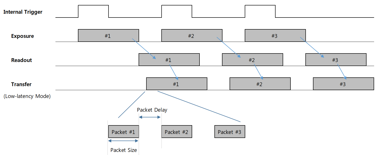
FPGA에서 전처리(Pre-processing)된 영상 데이터를 약 63MB의 Image Buffer(Frame Buffer)에 적재하고 읽어오는 방식을 선택할 수 있습니다. 초기값은 'Low-latency Mode Enable'이 'True'입니다. 이는 이미지가 Packet Size만큼 Buffer에 입력되면 즉시 전송하는 방식 입니다. 반면 'Low-latency Mode Enable'이 'False'로 설정된 경우에는 'Full-Framed Mode'가 되며 이미지 Frame이 모두 Buffering 되어야만 전송합니다.
두 모드는 촬상 및 Readout, 전처리까지의 소요 시간 및 타이밍은 동일 하지만, Host로의 전송을 시작하는 타이밍은 서로 다릅니다. 즉 트리거 입력부터 Host 수신까지의 총 소요시간에 차이가 있습니다.
| Low-Latency Mode | Full-Framed Mode | |
|---|---|---|
| Low-Latency_Mode_Enable Parameter | True | False |
| 전송 개시 시점 | Packet Size만큼 적재시 | Frame 모두 적재시 |
| Transfer Delay 사용 가능 여부 | 사용 불가 | 사용 가능 |
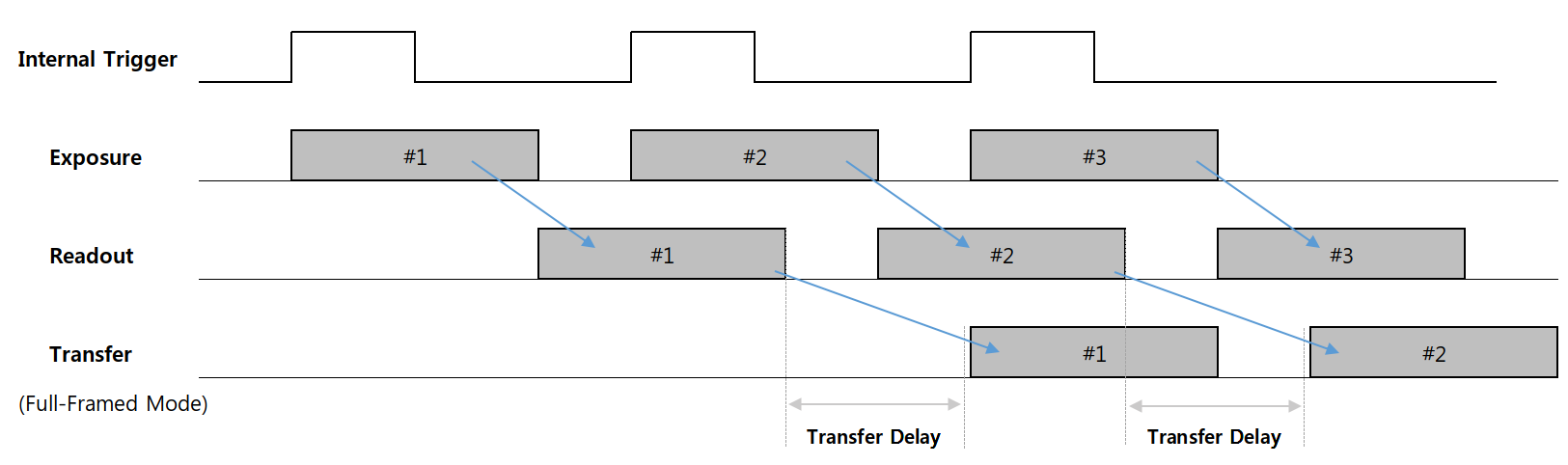
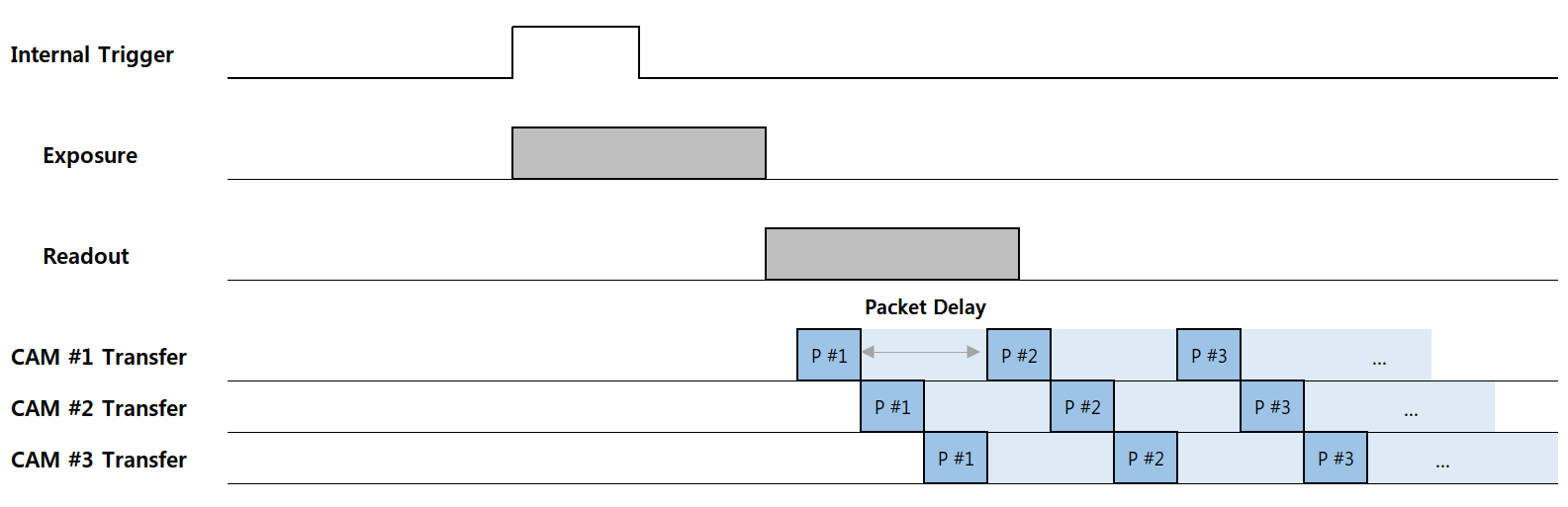
Host가 다수의 카메라로부터 영상을 입력받아야 하는 경우, 가장 좋은 방법은 각 Port마다 전용 Chipset이 부착된 Multi-port 랜카드를 사용하는 것 입니다. 그렇지 못한 경우에는 각 카메라의 Packet 전송을 분산시켜 Host(수신부)의 최대 Bandwidth를 초과하지 않도록 운용해야 합니다. 예컨대 'Full-Framed Mode'로 각기 다른 'Transfer Delay'를 적용하면 이미지 전송 시점을 분산시킬 수 있습니다. 이 경우 Host는 순차별로 이미지를 수신하게 됩니다.
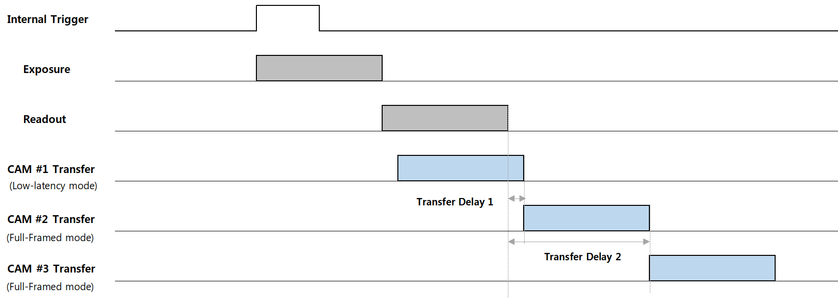
또한 'Low-Latency Mode'에서는 'Packet Delay'를 사용하면 이미지 Packet 간 Interval이 늘어나기 때문에 사이 시간을 활용하여 분산할 수 있습니다. 이 경우 Host는 여러 카메라의 이미지를 유사한 시간대에 수신하게 됩니다.
유의사항
1) 'Low-latency Mode Enable' 파라미터는 카메라의 재시작시 반영 됩니다. 따라서 모드 변경시 'Userset Save' 커맨드 이후 재부팅이 필요합니다.
2) 'Transfer Delay' 기능은 'Low-latency Mode Enable' 이 'False' 일 때에만 설정 가능합니다.
Heartbeat는 PC와 카메라가 연결되어 있을 때, 카메라는 영상 획득 상태가 아니더라도 연결 상태를 지속적으로 체크하는 기능입니다. 입력한 'Gev Heartbeat Timeout' 시간을 초과하도록 Heartbeat 패킷 (또는 응답)이 없을 경우, 연결이 끊어진 것으로 간주합니다. Host 및 카메라 모두 연결이 끊어졌다고 판단하면 기존의 연결을 해제 합니다.
Heartbeat Timeout 기능의 사용 여부를 결정할 수 있습니다. 'False'로 설정할 경우 Heartbeat 타이머가 작동됩니다. 만일 'Gev Heartbeat Disable'을 'True'로 설정할 경우 Heartbeat 기능은 비활성화 됩니다. 이 때에는 Link가 끊긴 경우 카메라 또는 Host에서는 Link 끊김을 감지할 수 없으므로 사용에 유의해야 합니다.
카메라가 전송할 이미지 패킷의 전송 단위 입니다. 가장 안정적인 이미지 패킷 전송은 이미지 Line Readout 과 동일한 주기로 전송하는 방법 입니다. 이에 따른 설정은 다음과 같습니다.
자세한 타이밍은 <Timing Diagram of 'Low-Latency Mode'> 그림을 참고해 주시기 바랍니다.
(단, n은 패킷 사이즈가 점보 프레임을 초과하지 않는 범위의 값).
카메라의 패킷 사이의 지연 시간을 추가하는 기능입니다. Packet Delay를 적용할 경우 패킷 간의 인터벌이 늘어나며 전송 대역폭이 낮아지는 효과가 있습니다. 설정 값은 Clock 단위로써 시간으로의 환산식은 다음과 같습니다.
유의사항
한 프레임 내에서 지연된 총 시간이 프레임 주기를 넘어설 경우 다음 프레임은 누락됩니다. 따라서 Frame Rate 손실이 발생합니다.
Camera Parameter List
| Category | Feature Name | R/W | Description |
|---|---|---|---|
| Device Control | DeviceVendorName | R | Vendor Name |
| Device Control | DeviceModelName | R | Model Name |
| Device Control | DeviceManufacturerInfo | R | Manufacturer Information |
| Device Control | DeviceVersion | R | Device Version |
| Device Control | DeviceID | R | Device serial number |
| Device Control | DeviceUserID | R/W | User configurable ID |
| Device Control | DeviceScanType | R | Scan type(Areascan/Linescan) |
| Image Format Control | Width | R/W | Width of the image provided by the device (in pixels). |
| Image Format Control | Height | R/W | Height of the image provided by the device (in pixels). |
| Image Format Control | PixelFormat | R/W | Format of the pixel provided by the device.(Mono8/Mono10/Mono12/Mono10Packed/Mono12Packed/BayerRG8/BayerRG10/BayerRG12/BayerRG10Packed/BayerRG12Packed/YUV422Packed/) |
| Image Format Control | WidthMax | R | Maximum width (in pixels) of the image. The dimension is calculated after horizontal binning, decimation or any other function changing the horizontal dimension of the image. |
| Image Format Control | HeightMax | R | Maximum height (in pixels) of the image. This dimension is calculated after vertical binning, decimation or any other function changing the vertical dimension of the image. |
| Image Format Control | OffsetX | R/W | Horizontal offset from the origin to the region of interest (in pixels). |
| Image Format Control | OffsetY | R/W | Vertical offset from the origin to the region of interest (in pixels). |
| Image Format Control | BinningVertical | R/W | Number of vertical photo-sensitive cells to combine together. This increases the intensity (or signal to noise ratio) of the pixels and reduces the vertical resolution (height) of the image. |
| Image Format Control | DecimationHorizontal | R/W | Horizontal sub-sampling of the image. This reduces the horizontal resolution(width) of the image by the specified horizontal decimation factor. |
| Image Format Control | DecimationVertical | R/W | Vertical sub-sampling of the image. This reduces the vertical resolution(height) of the image by the specified vertical decimation factor. |
| Image Format Control | TestImageSelector | R/W | Selects the type of test image that is sent by the device.(Off/GreyHorizontalRamp/GreyVerticalRamp) |
| Acquisition Control | AcquisitionStart | W | Starts the Acquisition of the device. The number of frames captured is specified by AcquisitionMode. |
| Acquisition Control | AcquisitionStop | W | Stops the Acquisition of the device at the end of the current Frame. It is mainly used when AcquisitionMode is Continuous but can be used in any acquisition mode. |
| Acquisition Control | AcquisitionMode | W | Sets the acquisition mode of the device. It defines mainly the number of frames to capture during an acquisition and the way the acquisition stops. |
| Acquisition Control | AcquisitionFrameCount | R/W | Number of frames to acquire in MultiFrame Acquisition mode. |
| Acquisition Control | TriggerSelector | R/W | Selects the type of trigger to configure.(FrameStart) |
| Acquisition Control | TriggerMode | R/W | Controls if the selected trigger is active.(Off/On) |
| Acquisition Control | TriggerSource | R/W | Specifies the internal signal or physical input Line to use as the trigger source. The selected trigger must have its TriggerMode set to On.(Line1/Software) |
| Acquisition Control | TriggerActivation | R/W | Specifies the activation mode of the trigger.(RisingEdge/FallingEdge) |
| Acquisition Control | TriggerSoftware | R/W | Generates an internal trigger. TriggerSource must be set to Software. |
| Acquisition Control | TriggerDelay | R/W | Specifies the delay in microseconds (us) to apply after the trigger reception before activating it. |
| Acquisition Control | ExposureMode | R/W | Sets the operation mode of the Exposure (or shutter).(Timed/TriggerWidth) |
| Acquisition Control | ExposureAuto | R/W | Sets the automatic exposure mode when ExposureMode is Timed. The exact algorithm used to implement this control is device-specific.(Off/Once/Continous) |
| Acquisition Control | ExposureTime | R/W | Sets the Exposure time (in microseconds) when ExposureMode is Timed and ExposureAuto is Off. This controls the duration where the photosensitive cells are exposed to light. |
| Acquisition Control | TransferDelay | R/W | Specifies the delay to apply after the image readout from sensor before transfer. This can be used as a crude flow-control mechanism if the application or the network infrastructure cannot keep up with the packets coming from the device. |
| Acquisition Control | AcquisitionFrameRate Enable | R/W | Activates the Acquisition Frame Rate function. |
| Acquisition Control | AcquisitionFrameRate | R/W | Controls the acquisition rate (in Hertz) at which the frames are captured. |
| Acquisition Control | AutoExposureTarget | R/W | Controls the analog black level as an absolute physical value. This represents a DC offset applied to the video signal. |
| Acquisition Control | Auto Exposure Time Lower Limit | R/W | The minimum exposure time of Auto Exposure. (unit : us) |
| Acquisition Control | Auto Exposure Time Upper Limit | R/W | The maximum exposure time of Auto Exposure. (unit : us) |
| Acquisition Control | Auto Gain Lower Limit | R/W | The minumum gain of Auto gain. |
| Acquisition Control | Auto Gain Upper Limit | R/W | The maximum gain of Auto gain. |
| Acquisition Control | Resulting Frame Rate | R | Resulting frame rate (in hertz) that maximum allowed frame acquisition. |
| Digital IO Control | LineSelector | R/W | Selects the physical line (or pin) of the external device connector to configure.(Line1/Line2) |
| Digital IO Control | Line Debouncer Time | R/W | Line Debouncer Time. unit : us |
| Digital IO Control | LineMode | R | The selected physical line is used to Input an electrical signal.(Input/Output) |
| Digital IO Control | LineInverter | R/W | Controls the invertion of the signal of the selected input or output Line. |
| Digital IO Control | LineStatus | R | Returns the current status of the selected input or output Line. |
| Digital IO Control | LineSource | R/W | Selects which internal acquisition or I/O source signal to output on the selected Line. LineMode must be Output.(Off/ExposureActive/TimerActive/UserOutput1) |
| Digital IO Control | UserOutputSelector | R/W | Selects which bit of the User Output register will be set by UserOutputValue.(UserOutput1) |
| Digital IO Control | UserOutputValue | R/W | Sets the value of the bit selected by UserOutputSelector. |
| Counter And Timer Control | Counter Selector | R/W | Selects which Counter to configure. |
| Counter And Timer Control | Counter Value | R | Reads the current value of the selected Counter. All counters are reset after Acquisition Start. |
| Counter And Timer Control | TimerSelector | R/W | Selects which Timer to configure.(Timer1) |
| Counter And Timer Control | TimerDuration | R/W | Sets the duration (in microseconds) of the Timer pulse. |
| Counter And Timer Control | TimerDelay | R/W | Sets the duration of the delay to apply at the reception of a trigger before to start the Timer. |
| Counter And Timer Control | TimerTriggerSource | R/W | Selects the source of the trigger to start the timer. |
| Event Control | Event Selector | R/W | Selects which event to signal to the host application. |
| Event Control | Event Notification | R/W | Activate or deactivate the notification to the host application of the occurrence of the selected event. |
| Analog Control | GainSelector | R/W | Selects which Gain is controlled by the various Gain features.(All) |
| Analog Control | GainRaw | R/W | Controls the selected gain as an absolute physical value. This is an amplification factor applied to the video signal. |
| Analog Control | GainAuto | R/W | Sets the automatic gain control (AGC) mode. The exact algorithm used to implement AGC is device-specific.(Off/Once/Continous) |
| Analog Control | BlackLevelSelector | R/W | Selects which Black Level is controlled by the various Black Level features.(All) |
| Analog Control | BlackLevelRaw | R/W | Controls the analog black level as an absolute physical value. This represents a DC offset applied to the video signal. |
| Analog Control | BalanceRatioSelector | R/W | Selects which Balance ratio to control.(Red/Green/Blue) |
| Analog Control | BalanceRatio | R/W | Controls ratio of the selected color component to a reference color component. It is used for white balancing. |
| Analog Control | BalanceWhiteAuto | R/W | Controls the mode for automatic white balancing between the color channels. The white balancing ratios are automatically adjusted. |
| Analog Control | Gamma Enable | R/W | Activates the gamma correction. Gamma correction can not be used simultaneously with the LUT. |
| Analog Control | Gamma | R/W | Controls the gamma correction of pixel intensity. |
| Analog Control | Noise Reduction Filter | R/W | Noise Reduction Filter. |
| LUT Control | LUTEnable | R/W | Activates the selected LUT. |
| LUT Control | LUTIndex | R/W | Control the index (offset) of the coefficient to access in the selected LUT. |
| LUT Control | LUTValue | R/W | Returns the Value at entry LUTIndex of the LUT selected by LUTSelector |
| User Set Control | UserSetSelector | R/W | Selects the feature User Set to load, save or configure.(Default/UserSet1/UserSet2/UserSet3) |
| User Set Control | UserSetLoad | R/W | Loads the User Set specified by UserSetSelector to the device and makes it active. |
| User Set Control | UserSetSave | R/W | Save the User Set specified by UserSetSelector to the non-volatile memory of the device. Default can not be save. |
| Color Transformation Control | ColorTransformationEnable | R/W | Activates the selected Color Transformation module. |
| Color Transformation Control | ColorTransformationValueSelector | R/W | Selects the Gain factor or Offset of the Transformation matrix to access in the selected Color Transformation module. ([B-Y] Gain (Positive) / [B-Y] Gain (Negative) / [B-Y] Hue (Positive) / [B-Y] Hue (Negative) / [R-Y] Gain (Positive) / [R-Y] Gain (Negative) / [R-Y] Hue (Positive) / [R-Y] Hue (Negative) / Crama Gain) |
| Color Transformation Control | ColorTransformationValue | R/W | Represents the value of the selected Gain factor or Offset inside the Transformation matrix. |
MCam40_SDK_V4.5.0(x64).exe : 윈도우 64비트용 설치 프로그램
MCam40_SDK_V4.5.0(x86).exe : 윈도우 32비트용 설치 프로그램
* 버전은 향후에 업데이트 될 수 있습니다.
 을 선택합니다.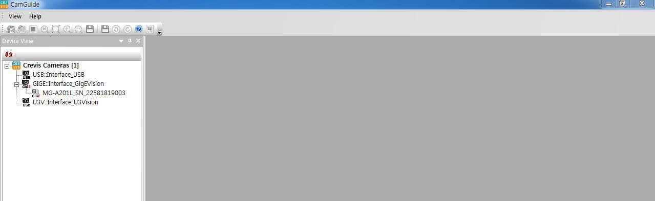
 을 클릭하여 재확인 바랍니다.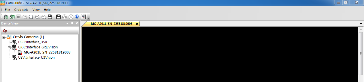
 을 선택합니다.
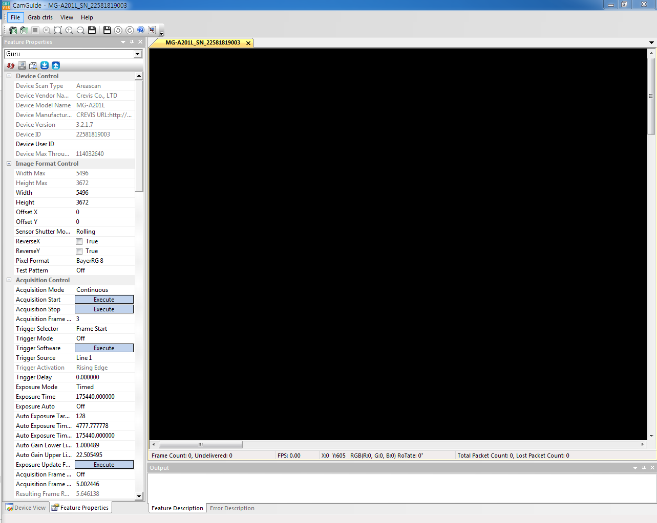
* 상세 설명은 CamGuide 매뉴얼 참조
| Revision | Date | Changes | Remark |
|---|---|---|---|
| 1.0 | 2019.5 | Issued | |
| 1.1 | 2021.02 | Minimum Exposure Time Exposure Start Delay, Exposure End Delay |
|
| 1.2 | 2021.08 | ◆ Frame Rate increasing by ROI (MG-A201R(L)-5 → MG-A121R(L)-9) ◆ 1HD Timing (MG-A500M(K)-22 : 21.98us -> 21.91us) |
|
| 1.3 | 2021.08 | Exposure Time Unit : 1HD → 1us Exposure Start Delay : 2HD~3HD → 3HD <Timing Diagram of 'Readout Over Trigger'> modified. |