4. Camera Functions
4.1.1 ROI (Region Of Interest)
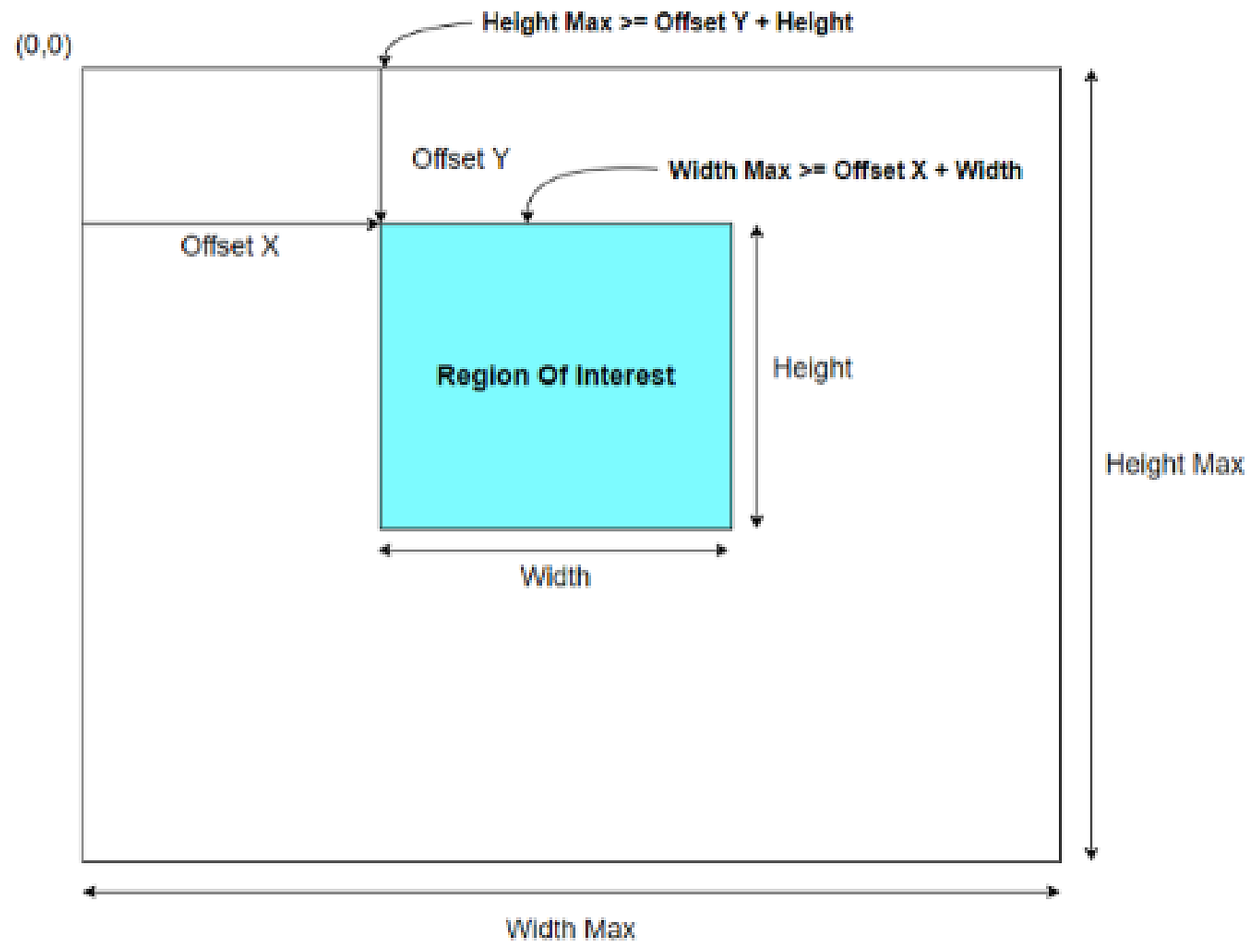
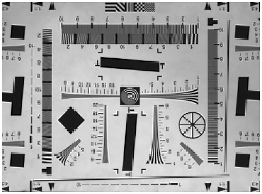
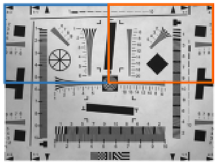
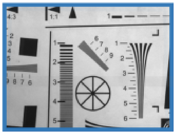
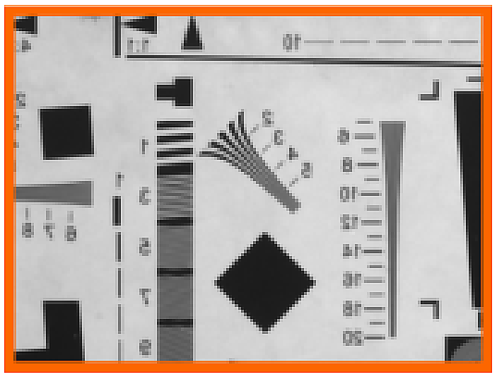
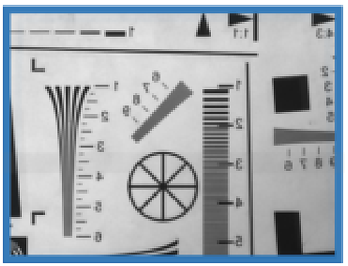
By setting Width, Height, Offset X, and Offset Y, you can output only the image of the desired area. Output Height
As the size gets smaller, the frame rate increases.
| Feature | Value | Description |
|---|
| WidthMax / HeightMax | (Read Only) | Maximum output size of the image. |
| Width / Height / Offset X / Offset Y | (Integer) | Changes the image output size and offset in pixel coordinates.
WidthMax ≥ Offset X + Width
HeightMax ≥ Offset Y + Height |
*Frame rate changes due to ROI can be checked through the ‘Resulting Frame Rate’ Feature.
*However, if 'Exposure Time' is longer than Frame Period (=1/Max.FrameRate), the Frame Rate may decrease. (Exposure
priority mode)
*The characteristics of 'Width' and 'Height' for each model are as follows.
Table 1 - Minimum & Unit Size of ROI| Model | Minimum Width | Minimum Height | Width Unit | Height Unit |
|---|
| All models | 176 | 8 | 16 | 4 |
4.1.2 Binning
This is a function that cumulatively reads adjacent pixels in the horizontal or vertical direction. Same as Decimation
While it has higher resolution, binning can also increase sensitivity by about two times because video signals are added.
Because digital binning is applied, the frame rate does not increase, but when ROI is applied together, the frame rate increases.
You can do it.
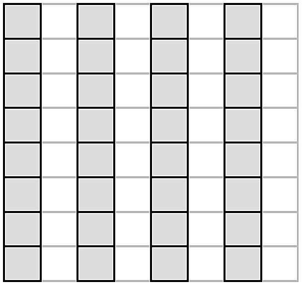
Original (1296 * 1032) Binning Horizontal (648 * 1032)
Binning Vertical (1296 * 516) Binning Horizontal, Vertical (648 * 516)
| Feature | Value | Description |
|---|
Binning Horizontal
Mode /
Binning Vertical Mode | Average | Selects the method for accumulating adjacent pixels.
- Average : Outputs the average of adjacent pixels
- Sum : Outputs the sum of adjacent pixels |
| Sum | |
Binning Horizontal
/ Binning Vertical | 1 | Reduces image resolution and accumulates adjacent pixels for output.
- 1 : Output original image
- 2 : Output binned image |
| 2 | |
*However, if 'Exposure Time' is longer than Frame Period (=1/Max.FrameRate), the Frame Rate may decrease. (Exposure
priority mode)
4.1.3 Decimation
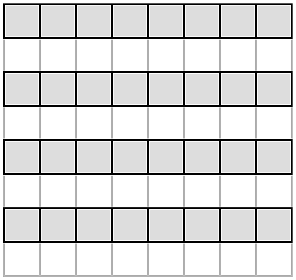
This is a function that reads quickly from the sensor, skipping 1 pixel in the horizontal or vertical direction. Year of Image
The resolution is reduced by half while the frame rate is increased.
DecimationHorizontal = 1
DecimationVertical = 1
DecimationHorizontal = 1
DecimationVertical = 2
DecimationHorizontal = 2
DecimationVertical = 1
| Feature | Value | Description |
|---|
| Decimation Horizontal / Decimation Vertical | 1 | Reduces image resolution and increases frame rate.
- 1 : Output original image
- 2 : Output decimated image |
| 2 | |
*The Frame Rate changed due to Decimation can be checked through the ‘Resulting Frame Rate’ Feature.
*However, if 'Exposure Time' is longer than Frame Period (=1/Max.FrameRate), the Frame Rate may decrease. (Exposure
priority mode)
4.1.4 Reverse
This is the function to output the image by inverting the left/right or top/bottom.
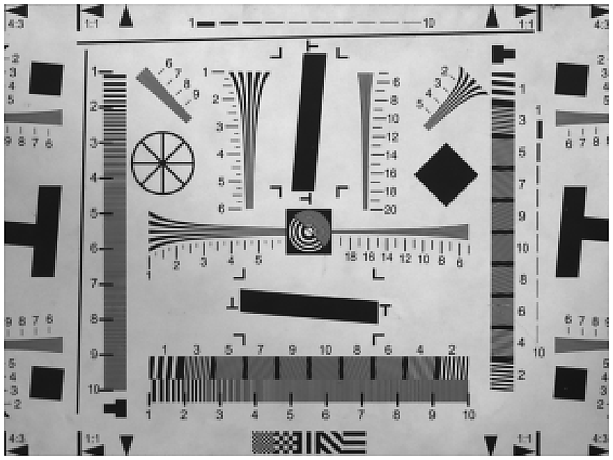
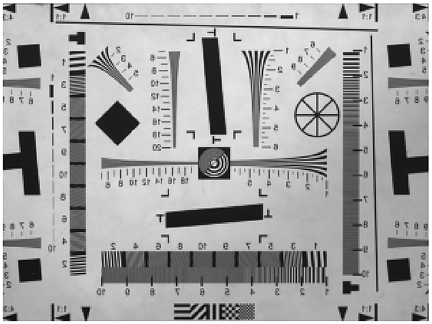
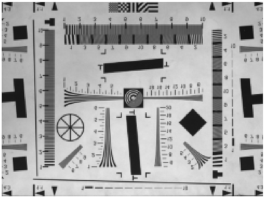
Original Reverse X
Reverse Y Reverse X, Y
| Feature | Value | Description |
|---|
| ReverseX / ReverseY | True | Flips the image horizontally or vertically. |
| False | |
*When ROI and Reverse are used simultaneously, the ROI function is applied from the reversed image. In other words, reverse as shown below.
When activated, the position of (0,0) Pixel, which is the starting coordinate of the Image, is reversed. Because of this, the same area as before applying Reverse
To capture an image, an Image Offset equal to Total Size – ROI Size is required.
Image Size : 2592 * 2056
Offset X : 0
Offset Y : 0
Reverse X : False
Reverse Y : False
Image Size : 1296 * 1028
Offset X : 0
Offset Y : 0
Reverse X : False
Reverse Y : False
Image Size : 1296 * 1028
Offset X : 0
Offset Y : 0
Reverse X : True
Reverse Y : False
Image Size : 1296 * 1028
Offset X : 1296
Offset Y : 0
Reverse X : True
Reverse Y : False
4.1.5 ADC Bit Depth
This is a function to set the bit depth when converting data from sensor to digital. Depending on the ADC Bit Depth setting
The Max Frame Rate is different, and in the same environment, the brightness of the video in 8bit mode is 10bit, and the brightness of the video is 12bit in 12bit mode.
It is about 4 times brighter than
| Feature | Value | Description |
|---|
| ADC Bit Depth | 8bit | Selects the sensor digital data depth. |
| 10bit | |
| 12bit | |
Set the Pixel Format of the image output from the camera. There is a difference in image transfer amount for each pixel format.
Therefore, the frame rate may change depending on the bandwidth.
| Feature | Value | Description |
|---|
| Pixel Format | Mono 8 | Sets the format of image data transmitted to the Frame Grabber. |
| Mono 10 | |
| Mono 12 | |
*The format of image data cannot be larger than the ‘ADC Bit Depth’ of the sensor.
*The 'Pixel Format' supported for each model is as follows.
Table 2 - Pixel Format Values| Model | Pixel Format Support |
|---|
| All models | Mono 8, Mono 10, Mono 12 |
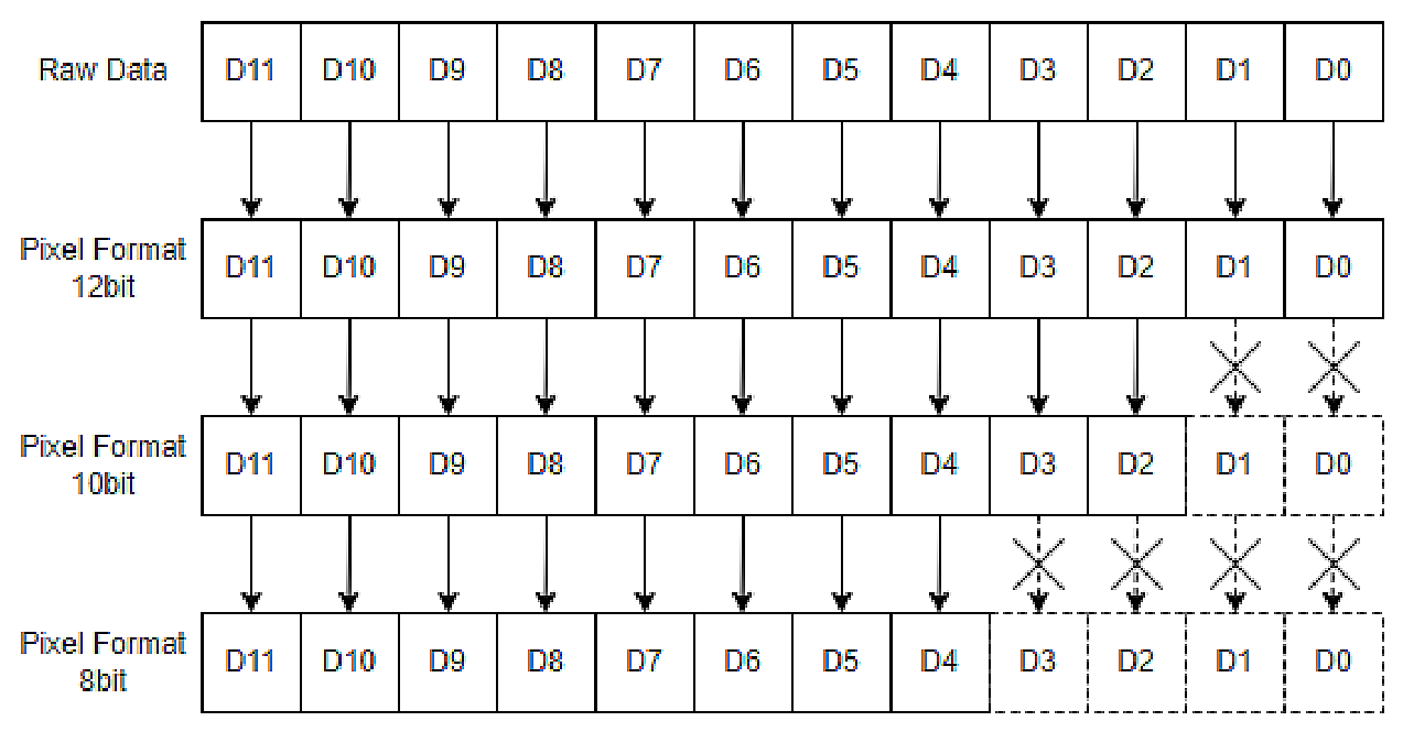
*Data processing method according to ‘Pixel Format’ is as follows.
4.1.7 Test Pattern
At the intermediate stage of image processing, the image is replaced with a test pattern and transmitted. Activate the Test Pattern function
Even if enabled, functions related to image acquisition such as ROI Size, Trigger input, and Acquisition Frame Rate are valid.
all. Test Pattern Image is created in 8bit gray level (0~255DN).
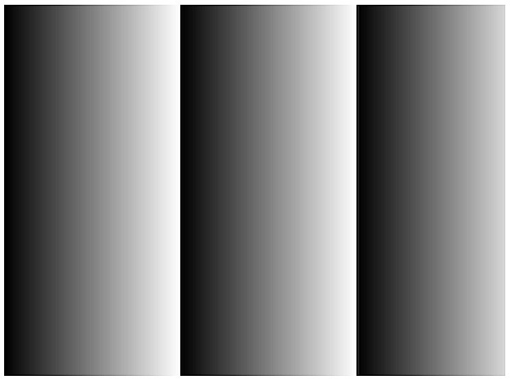
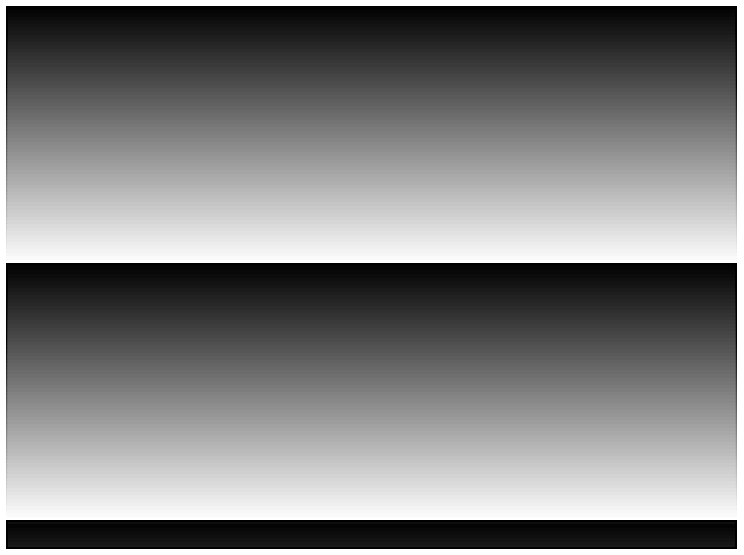
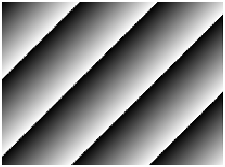
Grey Horizontal Ramp Grey Vertical Ramp Grey Horizontal Vertical Ramp
| Feature | Value | Description |
|---|
| Test Pattern | Off | Selects the test image.
- Off : Output sensor image
- Grey Horizontal Ramp : Brightness increases horizontally
- Grey Vertical Ramp : Brightness increases vertically
- Grey Horizontal Vertical Ramp : Brightness increases diagonally |
| Grey Horizontal
Ramp | |
| Grey Vertical
Ramp | |
| Grey Horizontal
Vertical Ramp | |
4.2 Acquisition Control
4.2.1 Acquisition Control
This is a function to set the camera's image acquisition time and method.
| Feature | Value | Description |
|---|
| Acquisition Mode | Continuous | Acquires images from the Acquisition Start command until the condition below.
- Continuous : Continues acquisition until the Acquisition Stop command |
| Acquisition Start | Command | Starts image acquisition by command input. |
| Acquisition Stop | Command | Stops image acquisition by command input. |
Acquisition Frame
Rate | 1 ~ Max.FPS | Sets the desired frame rate in Freerun Mode. |
Acquisition Frame
Rate Enable | Off | Enables or disables Acquisition Frame Rate in Freerun Mode. |
| On | |
| Resulting Frame Rate | (Read Only) | Outputs the actual camera frame rate in Freerun Mode. |
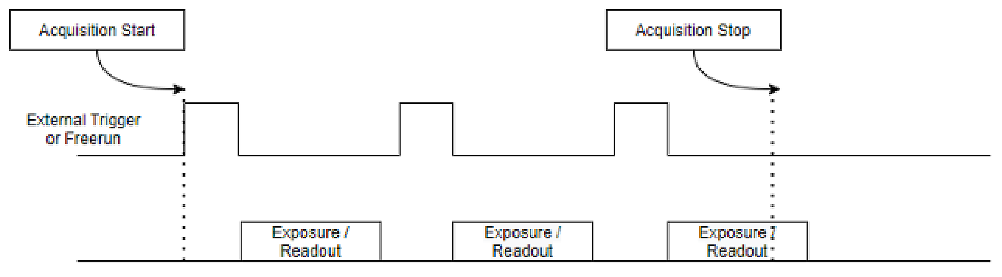
*After entering the 'Acquisition Start' command, the image is acquired by Internal Freerun Counter or External Trigger.
*The 'Acquisition Start' command is also input when executing streaming-related functions in the frame grabber dedicated program.
*Max.FPS changes depending on ROI, Decimation, 'Pixel Format', 'Exposure Time', and 'CXP Link Configuration' settings.
*Freerun Mode is ‘Trigger Mode’ = ‘Off’.
4.2.2 Exposure Control
Set the camera exposure method. Exposure start time is determined by Internal Freerun Counter or External Trigger.
Once determined, Timed Shutter exposes for the amount of time set in Exposure Time, and Trigger Width Shutter is a trigger.
Exposure is as much as the pulse width of the trigger in the mode. Exposure Time is set to Timed Shutter when Exposure Mode is set to Timed Shutter.
Applies only to right.
| Feature | Value | Description |
|---|
| Exposure Mode | Timed | - Timed : Exposure time is controlled by the Exposure Time setting
- Trigger Width : Exposure time is controlled by the pulse width of the external trigger |
| Trigger Width | |
| Exposure Time | 1 ~ 3,000,000
(Unit : us) | Sets the exposure time for Timed Shutter. |
*However, if 'Exposure Time' is longer than Frame Period (=1/Max.FrameRate), the Frame Rate may decrease. (Exposure
priority mode)
*If 'Trigger Mode' is 'Off' or 'Trigger Source' is 'Software', it operates as a 'Timed' Shutter.
*Set ‘Counter Event Source’ in the ‘Counter and Timer Control’ category to ‘Exposure Start’ or ‘Exposure Stop’
When you do this, the start and end times of exposure are output as 'Counter Value'. Current with 'Counter Update Feature' Command
You can update the counter. This Counter is initialized to 0 by the 'Counter Reset' Command.
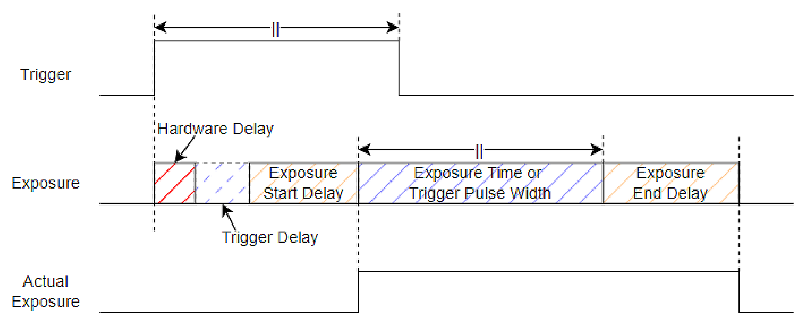
*There is a certain amount of time delay (Hardware Delay+Exposure Start Delay) from the external trigger input to the actual exposure of the sensor.
(Refer to Appendix B, C)
*There is an error (Exposure Offset) between 'Exposure Time' and the actual exposure time. (Refer to Appendix C)
Exposure Auto is a function where the camera automatically adjusts the Exposure Time to acquire an image with the desired brightness.
It can be used when Exposure Mode is Timed.
| Feature | Value | Description |
|---|
| Exposure Auto | Off | - Off : Set Exposure Time manually
- Once : Turns Exposure Auto off when the image reaches the target brightness
- Continuous : Continuously adjusts Exposure Time to maintain target brightness |
| Once | |
| Continuous | |
| Auto Exposure Target | 0 ~ 255
(DN @8bit) | Sets the desired average brightness. |
Auto Exposure Time
Lower Limit | 100 ~ 3,000,000
(Unit : us) | Sets the variable Exposure Time range for Exposure Auto.
Lower Limit ≤ Upper Limit |
Auto Exposure Time
Upper Limit | | |
Exposure Update
Feature | Command | Updates Exposure Time. |
*However, if 'Exposure Time' is longer than Frame Period (=1/Max.FrameRate), the Frame Rate may decrease. (Exposure
priority mode)
*If the 'Exposure Time' is too short, a flickering image may be obtained due to lighting, etc.
*When using 'Exposure Auto' and 'Gain Auto' at the same time, the operation varies depending on the brightness of the Image and Target.
*If the brightness of the image needs to be increased, 'Gain Auto' is applied after applying 'Exposure Auto'.
*If the brightness of the image needs to be reduced, 'Exposure Auto' is applied after applying 'Gain Auto'.
4.2.3 Trigger Mode Control
Controls image acquisition method and timing. The image acquisition method is largely Freerun Mode (Trigger Mode =
Off) and Trigger Mode, and the acquisition delay can be set.
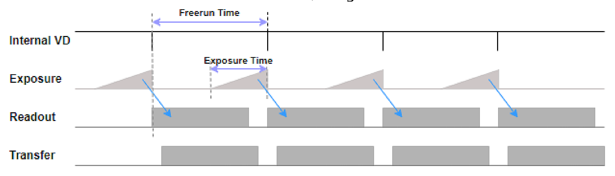
When Trigger Mode is Off, the camera operates in Freerun Mode. Freerun Mode operates in the current settings.
Internal Counter and VD signals are generated based on the maximum frame rate that can be achieved. Exposure set at the same time
An exposure signal is generated according to the time, operates the sensor, acquires the image, and transmits it to the frame grabber.
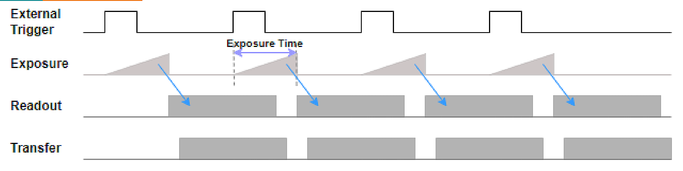
When Trigger Mode is On, the camera operates in Trigger Mode. Trigger Mode exposes with External Trigger.
You can also start and adjust the exposure time. Once the sensor completes exposure, the rest is the same as Freerun Mode.
The image is acquired and transmitted to the Frame Grabber.
| Feature | Value | Description |
|---|
| Trigger Mode | Off | - Off : Operates in Freerun Mode
- On : Operates in Trigger Mode |
| On | |
| Trigger Software | Command | Manually inputs a software trigger. |
| Trigger Source | CXP_Trigger | - CXP_Trigger : Trigger generated by the Frame Grabber
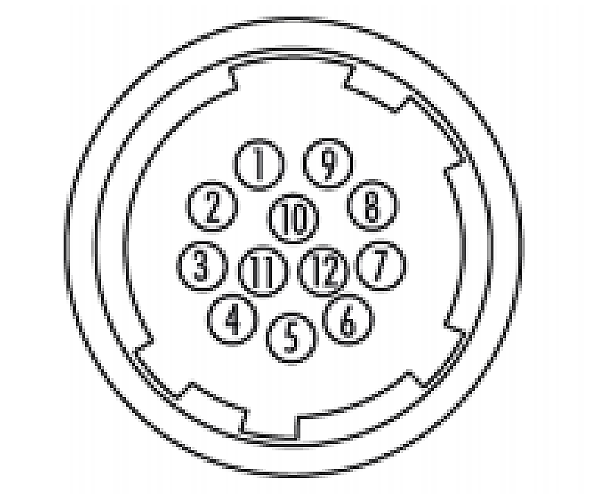
- Line 4 ~ 7 : External trigger through the 12-pin circular connector (see 3.5 External I/O Connector)
- Software : Trigger generated internally by the Trigger Software command |
| Line 4 | |
| Line 5 | |
| Line 6 | |
| Line 7 | |
| Software | |
| Trigger Activation | Rising Edge | Reference edge used by the camera to recognize the trigger. |
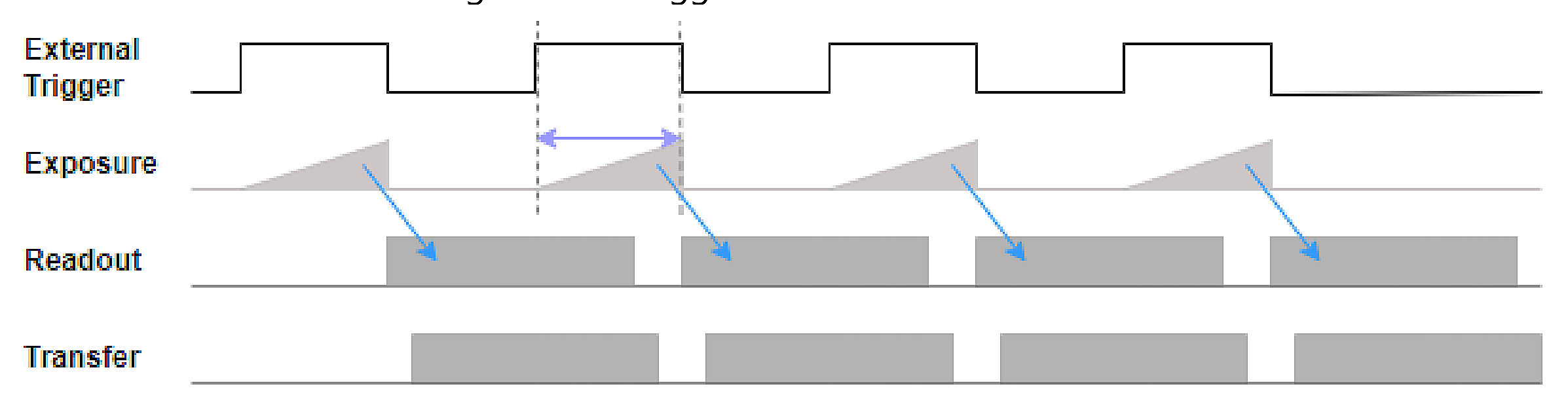
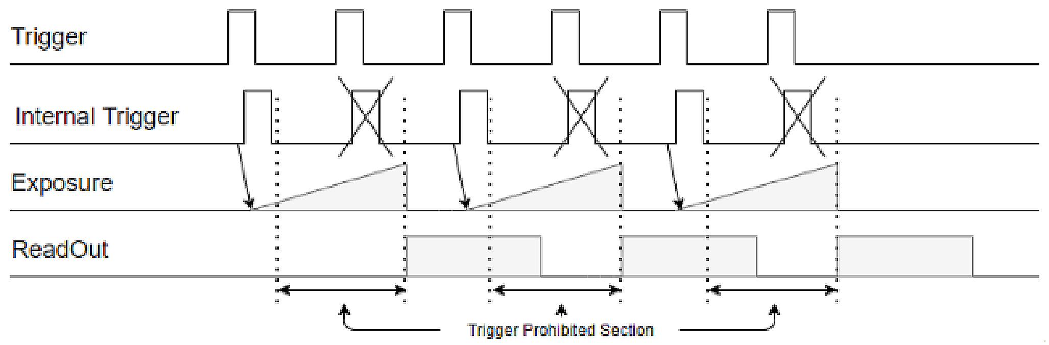
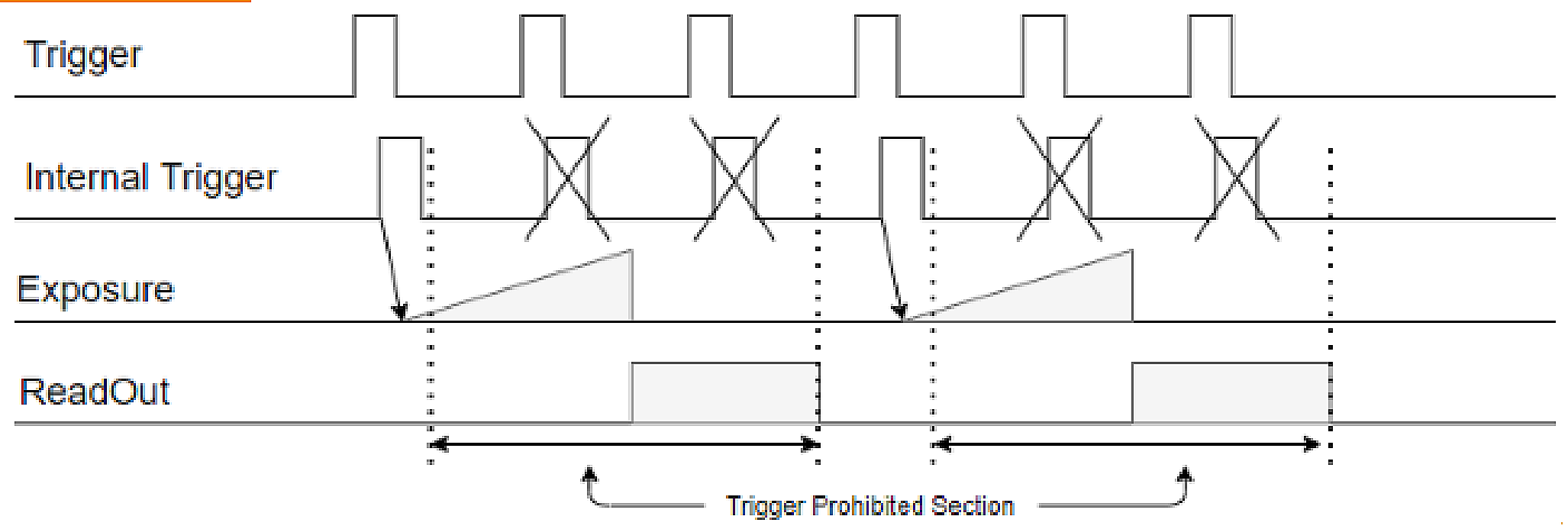
| Trigger Overlap | Off | - Off : Prevents the next exposure from starting during readout
- ReadOut : Allows the next exposure to start during readout |
| ReadOut | |
*In Freerun Mode, if 'Acquisition Frame Rate Enable' is 'On', it operates as 'Acquisition Frame Rate', and if 'Acquisition Frame Rate Enable' is 'Off', it operates as 'Acquisition Frame Rate'.
In this case, it operates at the maximum frame rate that can operate in the current settings.
*If 'Trigger Mode' is 'On', it is triggered by CXP Trigger, External Trigger, or Software Trigger according to the 'Trigger Source' setting.
It works.
*CXP Trigger must be set separately in the Frame Grabber program.
*'Trigger Activation' is fixed to 'Rising Edge', so you must use the 'Line Inverter' function to change the phase of the trigger.
do. (Refer to 4.3 Digital I/O Control)
*If you set 'Counter Event Source' in the 'Counter and Timer Control' category to 'External Trigger Start', the input will be triggered by the camera.
The total number of valid triggers is displayed as 'Counter Value'. Update the current counter with the ‘Counter Update Feature’ Command.
You can update. This Counter is initialized to 0 by the 'Counter Reset' Command.
*The operation according to the 'Trigger Overlap' setting is as follows.
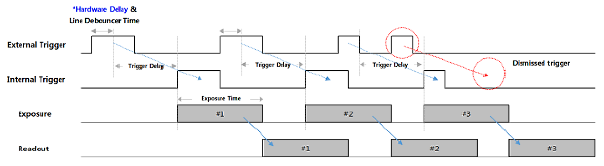
Trigger Delay is a function that operates by delaying the sensor's exposure for a certain period of time from the trigger input. camera
Trigger Delay is used when the timing of the input trigger does not match the timing of the external environment, such as lighting or the location of the subject.
You can obtain a clearer image using this.
Line Debounce Time is a function that removes chattering noise of the trigger signal passing through external I/O.
It's a skill. Since only signals that remain activated for more than a certain period of time are judged as valid inputs, delayed
Trigger is input.
| Feature | Value | Description |
|---|
| Trigger Delay | 0 ~ 3,000,000
(Unit : us) | Sets the delay time from trigger input to sensor exposure. |
| Line Debounce Time | 0 ~ 882
(Unit : us) | Sets Line Debounce Time. |
*New triggers entered while the trigger is delayed are ignored. If ‘Trigger Delay’ is greater than the input trigger period,
In case of missing trigger, the frame rate may decrease. (Refer to Figure 14)
*There is a certain amount of time delay (Hardware Delay+Exposure Start Delay) from the external trigger input to the actual exposure of the sensor.
(Refer to Appendix B, C)
4.3 Digital I/O Control
This function sets external I/O signals.
| Feature | Value | Description |
|---|
| Line Selector | Line 1 | Selects the line to configure.
- Line 1 : CXP Trigger
- Line 4, 5 : Direct I/O
- Line 6, 7 : OptoCoupled Input |
| Line 4 | |
| Line 5 | |
| Line 6 | |
| Line 7 | |
| Line Mode | Input | Sets input/output for the selected line.
Line 1, Line 6, and Line 7 support input only.
Line 4 and Line 5 support input/output. |
| Output | |
| Line Inverter | True | Sets the phase of the selected line.
- True : Inverts the line input/output phase by 180 degrees
- False : Keeps the line input/output phase |
| False | |
| Line Status | (Read Only) | Outputs the current status of the selected line. |
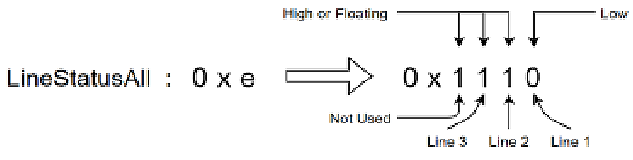
| Line Status All | (Read Only) | Outputs the current status of all lines as 4 bits. |
Line Status Update
Feature | Command | Updates the current status of all lines. |
*If 'Exposure Mode' is 'Trigger Width', 'Line Inverter' may affect the brightness of the image.
*In the case of 'Line Status' and 'Line Status All', 'True' is Logical High and 'False' is Logical Low.
*If the I/O Connector is not connected and is in a floating state, 'Line Status' outputs 'True'.
*Ex) 'Line Status All' = '0xe'
| Feature | Value | Description |
|---|
| Line Source | Off | Selects the waveform to output as the strobe signal.
- Off : Strobe off
- Timer Active : Outputs Timer Strobe signal (see 4.4.2 Timer Control)
- Exposure Active : Outputs a strobe signal active during actual exposure
- User Output 1, 2 : Outputs User Output Value as the strobe signal |
| Timer Active | |
| Exposure Active | |
| User Output 1 | |
| User Output 2 | |
| User Output Selector | User Output 1 | Selects the User Output to configure. |
| User Output 2 | |
| Feature | Value | Description |
|---|
| User Output Value | True | - True : Sets the selected User Output to High
- False : Sets the selected User Output to Low |
| False | |
4.4 Counter and Timer Control
4.4.1 Counter Control
This function monitors camera movement. The process where a camera receives a trigger, exposes it, and outputs an image.
You can monitor with a step-by-step counter. In addition, camera specifications such as trigger input at a speed faster than the frame cycle
It is possible to check for signal input exceeding .
| Feature | Value | Description |
|---|
| Counter Event Source | External Trigger
Start | Selects the counter.
- External Trigger Start : Number of external/software trigger inputs
- Exposure Start : Number of exposure starts
- Exposure Stop : Number of exposure stops
- Frame End : Number of readout frames
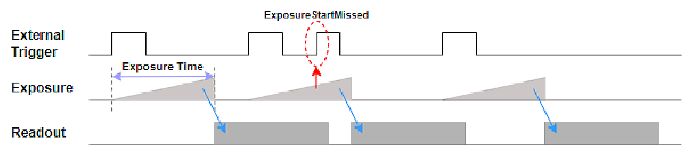
- Exposure Start Missed : Number of trigger inputs during exposure
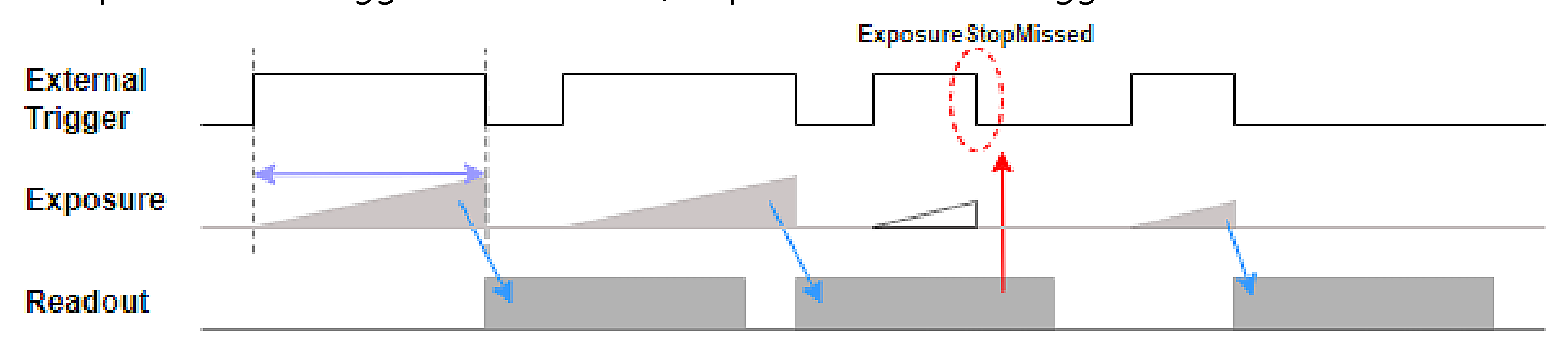
- Exposure Stop Missed : Number of exposure stops during readout |
| Exposure Start | |
| Exposure Stop | |
| Frame End | |
| Exposure Start
Missed | |
| Exposure Stop
Missed | |
| Counter Value | (Read Only) | Outputs the value of the selected counter. |
| Counter Reset | Command | Resets all counter values to 0. |
Counter Update
Feature | Command | Updates Counter Value. |
*'Exposure Start Missed' can increase when 'Trigger Mode' = 'On' and 'Exposure Mode' is 'Timed'.
*'Exposure Stop Missed' can increase when 'Trigger Mode' = 'On' and 'Exposure Mode' is 'Trigger Width'.
4.4.2 Timer Control
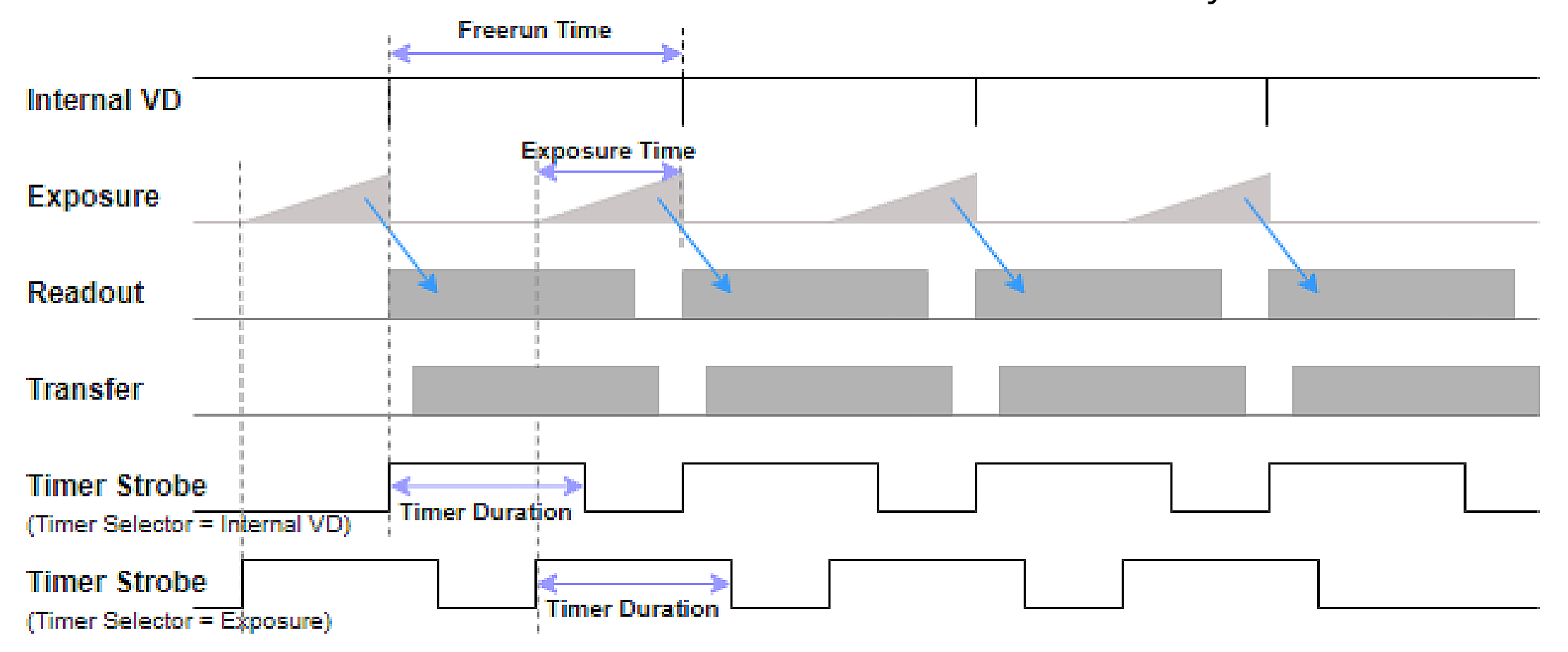
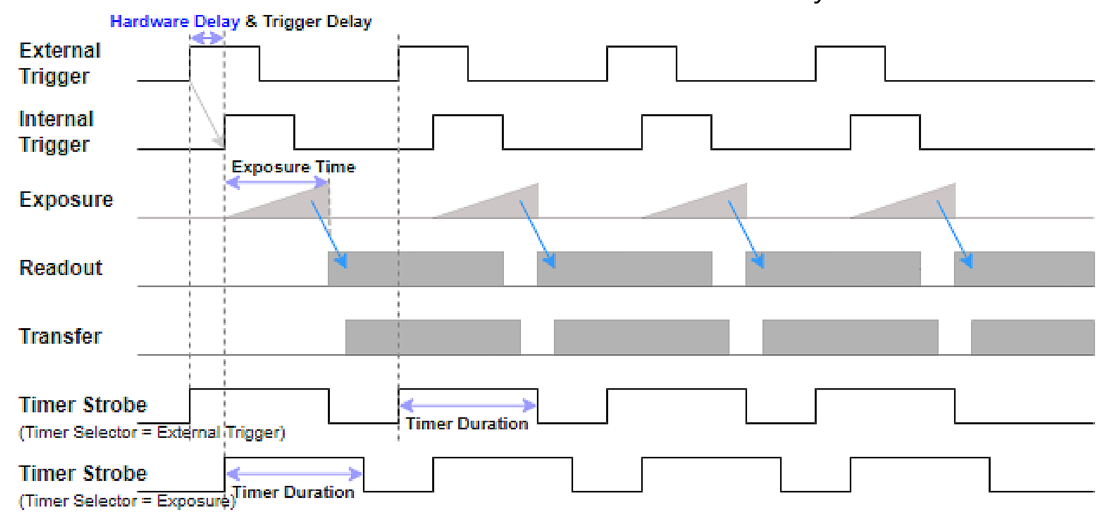
This is a function to set the strobe signal output outside the camera. In Freerun Mode, Timer Strobe signal is not generated.
The starting point can be set to the exposure start or Internal VD Start point. The point at which the VD is initialized is Shutter
Since the timing of operation is different, a Timer Delay may be necessary to synchronize with the lighting.
In Trigger Mode, the generation time of the Timer Strobe signal is set to the start of exposure or external trigger input.
You can do it. When creating a Timer Strobe at the time of External Trigger input, Trgger Delay and Hardware
Timer Delay may be necessary to synchronize with the actual exposure time that is delayed due to the delay.
| Feature | Value | Description |
|---|
| Timer Selector | Exposure | Selects the Timer Strobe start point.
- Exposure : Outputs Timer Strobe based on the actual exposure start
- External Trigger : Outputs Timer Strobe based on trigger input
- Internal VD : Outputs Timer Strobe based on Internal Counter Reset |
| External Trigger | |
| Internal VD | |
| Timer Duration | 0 ~ 3,000,000
(Unit : us) | Sets the pulse width of Timer Strobe. |
| Timer Delay | 0 ~ 3,000,000
(Unit : us) | Sets the Timer Strobe output delay from the selected start point. |
*In Trigger Mode, the Internal Counter does not operate, so 'Internal VD' cannot be used.
4.5 Analog Control
4.5.1 Gain Control
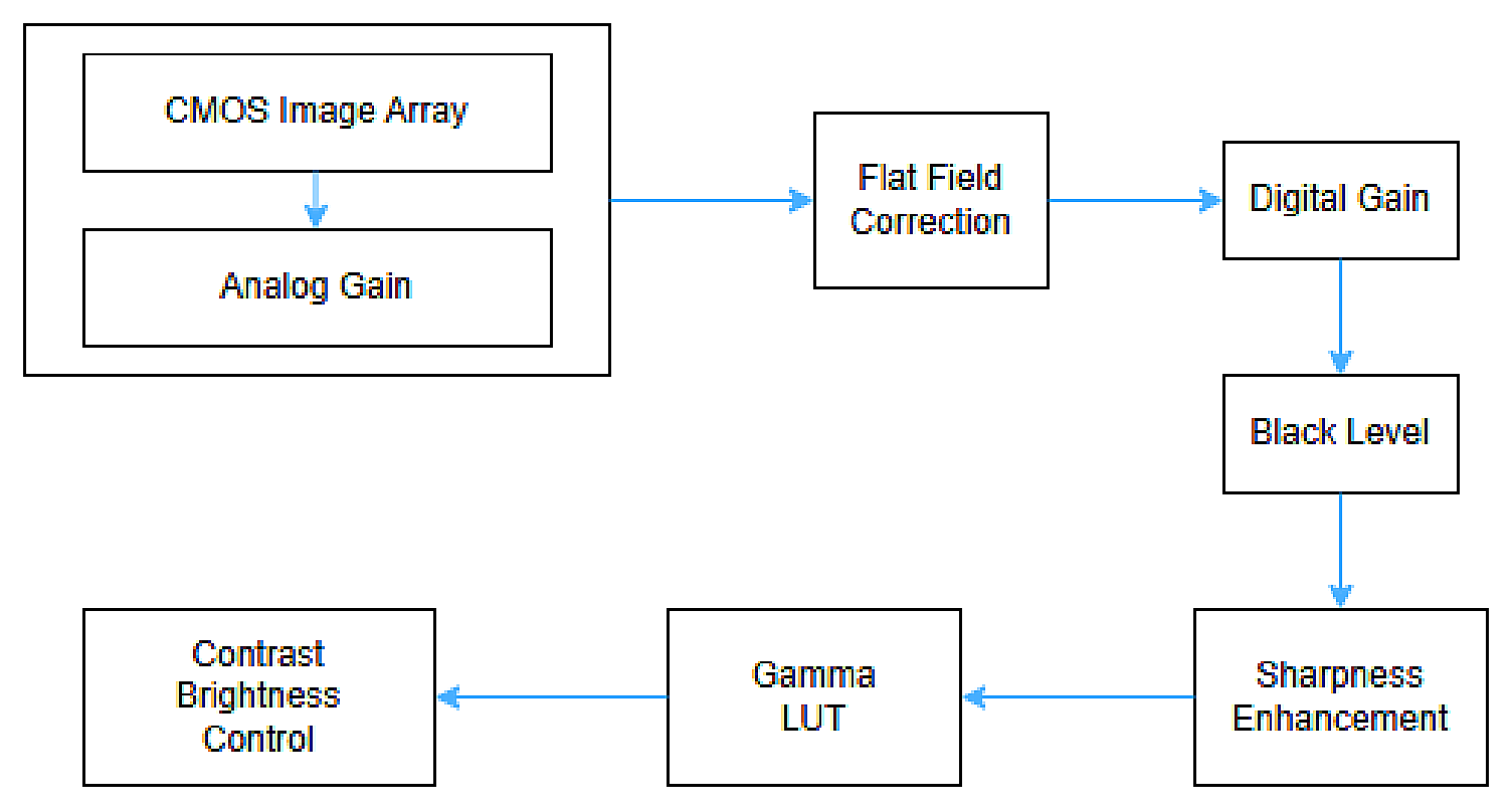
This function adjusts gain. The sensitivity of the image can be improved without reducing the frame rate, but the
Noise may also increase.
| Feature | Value | Description |
|---|
| Gain Selector | All | Selects the gain to configure. The two gains are independent and can be set to different values.
- All : Sensor Analog Gain
- DigitalAll : Digital Gain |
| DigitalAll | |
| Gain Raw | All : 0 ~ 240
DigitalAll : 0 ~
7168 | Sets the selected gain as a raw value. Sensor Analog Gain raw range varies by product and setting. |
| Gain Abs | All : 1x ~ 16x
DigitalAll : 1x ~
8x | Sets the selected gain as a multiplier. Sensor Analog Gain absolute range varies by product and setting. |
*'Gain Raw' and 'Gain Abs' supported for each model are as follows.
Table 3 - Analog Gain Values| Model | Analog Gain Raw Support | Analog Gain Abs Support |
|---|
| HX-A130SW | 0~60(ADC 8), 0 ~ 180(ADC 10, 12) | 1x ~ 2x(ADC 8), 1x ~ 8x(ADC 10, 12) |
| HX-A530SW | 0 ~ 240 | 1x ~ 16x |
Gain Auto is a function where the camera automatically adjusts the analog gain to obtain an image with the desired brightness.
| Feature | Value | Description |
|---|
| Gain Auto | Off | - Off : Set Gain manually
- Once : Turns Gain Auto off when the image reaches target brightness
- Continuous : Continuously adjusts Gain to maintain target brightness |
| Once | |
| Continuous | |
| Gain Update Feature | Command | Updates Gain. |
*The target of 'Gain Auto' is 'Auto Exposure Target'.
*When using 'Gain Auto' and 'Exposure Auto' at the same time, the operation varies depending on the brightness of the Image and Target.
*If the brightness of the image needs to be increased, 'Gain Auto' is applied after applying 'Exposure Auto'.
*If the brightness of the image needs to be reduced, 'Exposure Auto' is applied after applying 'Gain Auto'.
4.5.2 Black Level Control
This function adjusts the black level. You can change the Offset of the Image.
| Feature | Value | Description |
|---|
| Black Level Selector | All | Selects the Black Level to configure.
- All : Sensor Analog Black Level
- DigitalAll : Digital Black Level |
| DigitalAll | |
| Black Level | 0 ~ 4095 | Sets the selected Black Level.
- All : 0 ~ 255 (ADC 8bit), 0 ~ 1023 (ADC 10bit), 0 ~ 4095 (ADC 12bit)
- DigitalAll : 0 ~ 4095 |
4.5.3 Gamma Control
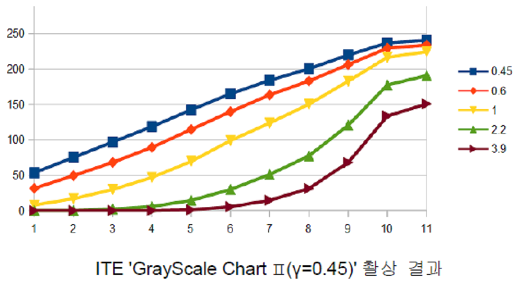
This is a function to adjust gamma. You can correct the contrast of the image.
| Feature | Value | Description |
|---|
| Gamma Enable | True | Enables or disables Gamma. |
| False | |
| Gamma | 0 ~ 3.99 | Sets Gamma. |
*The Gamma function cannot be used simultaneously with the LUT function. When the Gamma function is enabled, the LUT function is disabled.
4.6 LUT Control
The LUT (Look Up Table) function is a function that converts digital pixel values by matching them 1:1 to the output value of the table's input value.
no see. Each Index (Input Image) in the table is replaced with a pixel of a predefined LUT Value (Output Image).
| Feature | Value | Description |
|---|
| LUT Enable | True | Enables or disables LUT. |
| False | |
| LUT Index | 0 ~ 1023 | Selects the LUT Index. |
| LUT Value | 0 ~ 1023 | Sets the output value of the selected LUT Index. |
*The LUT function cannot be used simultaneously with the Gamma function. When the LUT function is enabled, the Gamma function is disabled.
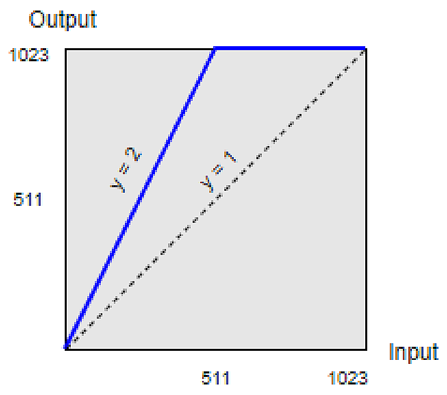
*Ex) When using a table in the form of y=2x, low-illuminance pixels can see an improvement in sensitivity, while high-illuminance pixels are saturated.
Therefore, loss in dynamic range occurs.
Table 4 - LUT Data| Index | 0 | 1 | 2 | 3 | ... | 256 | ... | 510 | 511 | 512 | 513 |
|---|
| Value | 0 | 2 | 4 | 6 | … | 512 | ... | 1022 | 1023 | 1023 | 1023 |
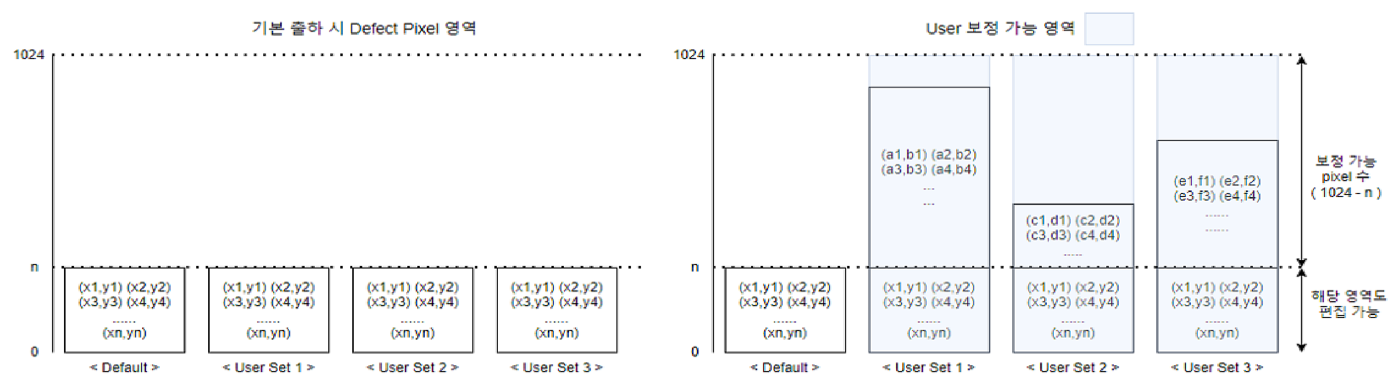
4.7 Defect Pixel Control
This function manages the camera’s defect pixels. Correction is made for defective pixels at the time of shipment. but use
You can correct pixels that you consider to be bad pixels by additionally defining them. Camera's User Set 1 to 3 area
Up to 1024 defective pixels can be saved.
| Feature | Value | Description |
|---|
| DefectFilter Enable | Off | Enables or disables Defect Filter. |
| On | |
| Defectfilter Test Mode Selector | Off | Checks the position of pixels where Defect Filter is applied.
- Off : Output sensor image
- Mark Black : Mark defect pixels as dark pixels
- Mark White : Mark defect pixels as white pixels
- Mark White with Black Background : Mark defect pixels as white pixels on a black background |
| Mark Black | |
| Mark White | |
| Mark White with Black Background | |
| Defect Pixel Replace Count | 1 ~ 1024 | Number of defect pixels to correct. |
| Defect Pixel Index | 0 ~ 1023 | Index of the defect pixel to correct. |
| Feature | Value | Description |
|---|
| Defect Pixel X Coordinate | 0 ~ WidthMax-1 | X-axis coordinate of the defect pixel to correct. Pixel coordinates start from 0. |
| Defect Pixel Y Coordinate | 0 ~ HeightMax-1 | Y-axis coordinate of the defect pixel to correct. Pixel coordinates start from 0. |
| Defect Pixel Replacement | Command | Applies the entered defect pixel information. |
*Ex) 제품 출하 시 20개의 Defect Pixel이 보정된 상태에서 사용자가 두 개의 Pixel을 추가하는 경우
Table 5 - User Define ExampleDefectPixel
ReplaceCount | DefectPixel
Index | DefectPixel
XCoordinate | DefectPixel
YCoordinate | Remarks |
|---|
| 19 | 18 | ... | ... | Factory Defined |
| 20 | 19 | ... | ... | Factory Defined |
| 21 | 20 | (156, 31) | (1131, 125) | User Defined |
| 22 | 21 | (208, 114) | (321, 611) | User Defined |
*보정 이후에는 'User Set Save' Command를 이용하여 원하는 User Set 영역에 저장해야 합니다.
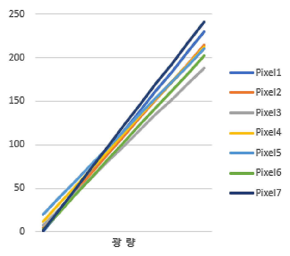
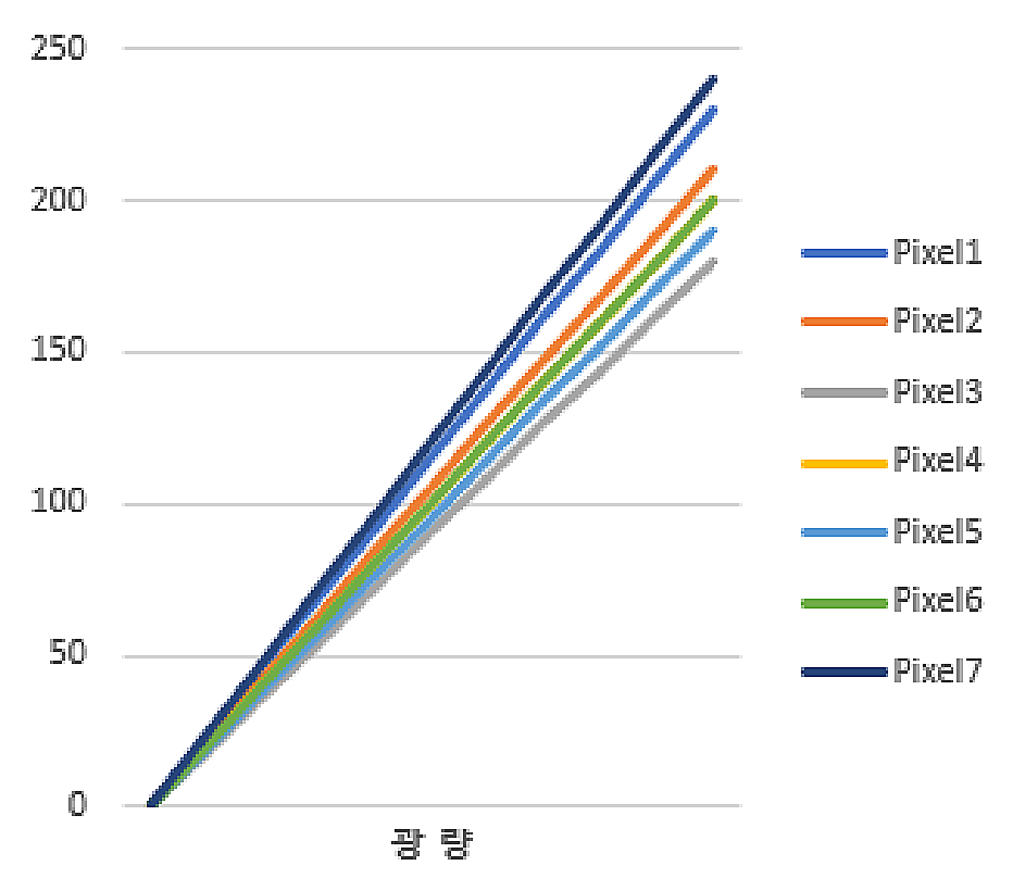
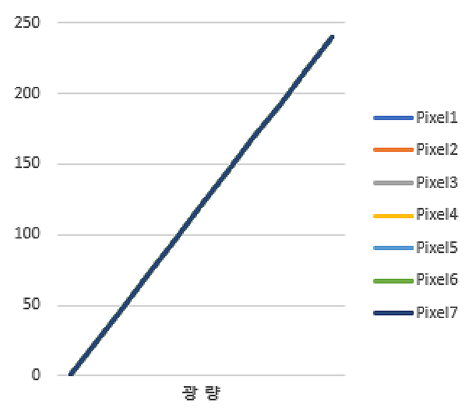
4.8 Flat Field Correction
Flat Field Correction (FFC) is a function that uniformly corrects the brightness value of the captured image. Brightness value is not uniform
Other causes include the influence of lens shadows, uneven lighting brightness, and differences in sensitivity of each sensor pixel.
| Feature | Value | Description |
|---|
| FFC Enable | Off | Enables or disables FFC. |
| On | |
Calibration Image
Count | 1 ~ 4 | Sets the number of images to use for calibration. |
| FFC High Gain Enable | True | Enables or disables FFC High Gain.
- True : Gain is applied up to 5x during White Calibration
- False : Gain is applied up to 3x during White Calibration |
| False | |
PRNU Target
Threshold | 1 ~ 50
(Unit : %) | Sets the target brightness among all pixels during White Calibration. |
*The FFC methods supported by model are as follows.
Table 6 - FFC Mode| Model | FFC |
|---|
| All models | Pixel by Pixel |
Original Data Black Calibration White Calibration
| Feature | Value | Description |
|---|
| Black Calibration | Command | Runs Black Calibration. |
| White Calibration | Command | Runs White Calibration. |
FFC Save Load Flash
Select | 0 ~ 3 | Selects the area for saving/loading FFC data. |
| FFC Save | Command | Saves FFC data to the selected flash area. |
| FFC Load | Command | Loads FFC data from the selected flash area. |
| FFC Abort | Command | Forcefully aborts the currently running FFC function. |
FFC Function Process
Status | (Read Only) | Checks the operating status of the FFC function.
- Complete : FFC function complete
- Get Black Image : Acquiring black image
- Get White Image : Acquiring white image
- Black Calibrating : Black calibration in progress
- White Calibrating : White calibration in progress
- FFC Erasing : Erasing FFC data
- FFC Saving : Saving FFC data
- FFC Loading : Loading FFC data |
FFC Function Process
Status Update Feature | Command | Updates FFC Function Process Status. |
*To stabilize power consumption and temperature, when the FFC function is disabled, FFC-related functions do not operate. ‘FFC Enable’
After changing it to 'On', you must perform Calibration, Save, Load, etc.
*Defect correction must be performed before FFC, and calibration must be performed under the condition that the defect filter is enabled for accurate correction.
Images can be printed.
*'Black Calibration' must precede 'White Calibration', and 'Black Calibration' and 'White Calibration' must be performed before product shipment.
Calibration is performed before shipment. Perform ‘White Calibration’ in the actual usage environment (lens fastening, etc.) to
The brightness difference can be corrected, and if necessary, you can start again from 'Black Calibration'.
Black Calibration corrects the image in an environment with zero light intensity (shielding).
Before After
White Calibration acquires and corrects bright images from actual use environments (lenses, etc.). A subject with uniform brightness
By capturing an object (or lighting), the image is less than 200 DN on average, shading the edge of the sensor or other external environments.
Correct the brightness difference as shown in the graph below.
Before After
4.9 Sharpness Enhancement
Sharpness Enhancement is a function that emphasizes the outlines in an image and makes them sharper. Sharpness
Depending on the enhancement setting, you can obtain a clearer image, but noise may also be emphasized.
| Feature | Value | Description |
|---|
| Sharpness Enable | Off | Enables or disables Sharpness. |
| On | |
| Sharpness Strength | 0 ~ 15.996 | Sets the strength of Sharpness Enhancement. |
| Sharpness Filter Size | 0.001 ~ 4 | Sets the Sharpness Enhancement filter size. |
*Ex) Sharpness Filter Size = 1.5
Sharpness Strength = 0 Sharpness Strength = 4 Sharpness Strength = 8
4.10 Contrast Brightness Control
4.10.1 Contrast
Contrast adjusts the contrast of the image.
Contrast 0 Contrast 40 Contrast 60
| Feature | Value | Description |
|---|
| Contrast | -99 ~ 99 | Adjusts contrast. |
4.10.2 Brightness
Brightness adjusts the brightness of the image. The setting value of 512 (based on 12 bit) increases the brightness by approximately 32 DN in an 8 bit video.
Let's go.
Brightness 0 Brightness 512 Brightness 1024
| Feature | Value | Description |
|---|
| Brightness | -2047 ~ 2047
(Unit : 12bit DN) | Adjusts brightness. |
4.10.3 Histogram Stretch
You can correct the image using Histogram Stretch. If Histogram Stretch Min is set to 800,
The setting value of 800 (based on 12bit) is about 50DN in an 8bit video, so the video is output by stretching 50DN to 0DN.
all. When Histogram Stretch Max is set to 2400, the setting value of 2400 (based on 12bit) is about 150DN in 8bit video.
Therefore, the video is output by stretching 150DN to 255DN.
Min 0 / Max 0 Min 800 / Max 2400 Min 1120 / Max 2400
| Feature | Value | Description |
|---|
| Histogram Stretch Min | -2,147,483,648 ~
Histogram
Stretch Max-1
(Unit : 12bit DN) | Sets the Histogram Min value. Brightness corresponding to the setting is stretched to 0. |
Histogram Stretch
Max | Histogram
Stretch Min+1 ~
2,147,483,647
(Unit : 12bit DN) | Sets the Histogram Max value. Brightness corresponding to the setting is stretched to 4095. |
*Ex) When Min = 320, Max = 2000 are set, 20DN and 125DN based on 8 bits are stretched to 0DN and 255DN, respectively.
4.10.4 Auto Contrast
Auto Contrast is a function that automatically corrects the image by setting the factor and target. The factor setting value is set to the target.
Correct the image by stretching it to the set value. Factor Low and Factor High are the lowest and lowest pixels in the entire image, respectively.
This is the upper percentage value, and Target Low and Target High are 12bit DN values (0~4095).
| Feature | Value | Description |
|---|
| Auto Contrast Mode | Off | - Off : Manually set Contrast and Brightness
- Once : Turns Auto Contrast off when each factor reaches the target brightness
- Continuous : Continuously adjusts Contrast and Brightness |
| Once | |
| Continuous | |
Auto Contrast Factor
Low | 0 ~ 50
(Unit : %) | Sets Auto Contrast Factor Low. This is the lower percentile of all image pixels. |
Auto Contrast Factor
High | 0 ~ 50
(Unit : %) | Sets Auto Contrast Factor High. This is the upper percentile of all image pixels. |
Auto Contrast Target
Low | 0 ~ Auto
Contrast Target
High-1
(Unit : 12bit DN) | Sets Auto Contrast Target Low. Brightness (DN) corresponding to Auto Contrast Factor Low is stretched to the target brightness (DN). |
| Feature | Value | Description |
|---|
| Auto Contrast Target High | Auto Contrast Target Low+1 ~ 4095
(Unit : 12bit DN) | Sets the Auto Contrast Target High value. Brightness (DN) corresponding to Auto Contrast Factor High is stretched to the target brightness (DN). |
| Contrast Update Feature | Command | Updates Contrast, Brightness, Histogram Stretch Min, and Histogram Stretch Max. |
*If the original video is too dark, noise may increase.
4.11 Sensor Cooling Control
This function controls the sensor temperature. The sensor temperature that guarantees the best quality is 15℃. for this
A thermoelectric cooler is built inside the sensor.
Sensor temperature can be controlled automatically/manually. In automatic mode, the Sensor Cooling Target set temperature (℃) is
Applies to Cooling. Voltage is controlled by comparing sensor temperature and case temperature in real time. Manual mode is
Regardless of the target temperature, the Sensor Cooling Voltage set voltage (V) is applied to cooling. both modes
The voltage applied to actual cooling can be checked in Sensor Cooling Applied Voltage. The default setting is
Same mode, target temperature is 15℃.
| Feature | Value | Description |
|---|
| Sensor Cooling Auto | Off | Enables or disables Sensor Cooling Auto. |
| On | |
| Sensor Cooling Target | 10 ~ 40
(Unit : ℃) | Sets the sensor target temperature. This setting is valid only when Sensor Cooling Auto is On. |
Sensor Cooling
Voltage | -6 ~ 6
(Unit : V) | Sets the voltage applied to sensor cooling. This setting is valid only when Sensor Cooling Auto is Off. |
Sensor Cooling
Applied Voltage | (Read Only)
(Unit : V) | Actual voltage applied to cooling. |
Sensor Cooling
Voltage Feature | Command | Updates Sensor Cooling Applied Voltage. |
*Sensor temperature and case temperature can be found in ‘Device Temperature Selector’ and ‘Device Temperature’ in the ‘Device Control’ category.
You can check. You can update the current temperature using the 'Temperature Update Feature'.
*The case temperature displayed in 'Device Temperature' and the case temperature applied to the cooling algorithm are those of the camera's internal frame.
It's temperature.
*Power consumption may increase depending on the degree of sensor cooling. Target temperature (automatic) considering power consumption and image quality
mode) or voltage (manual mode).
*The maximum cooling range of the built-in thermoelectric cooler is 40℃. In automatic mode, the sensor temperature and case temperature
The target temperature is automatically adjusted so that the difference does not exceed 40℃. Therefore, the case temperature is 40℃ higher than the target temperature.
If it rises, the sensor temperature may also rise, and additional heat dissipation measures must be taken as necessary.
*Heat generation may increase depending on the voltage applied to cooling. When setting voltage in manual mode, Sensor temperature and Case
Both temperature and ambient temperature must be considered.
4.12 User Set Control
This is a function to save or load values set by the user.
| Feature | Value | Description |
|---|
| User Set Selector | Default | Selects the area to save/load.
- Default : Factory settings area; User Set Load only
- User Set 1, 2, 3 : User-configurable save/load areas |
| User Set 1 | |
| User Set 2 | |
| User Set 3 | |
| User Set Load | Command | Loads camera settings from the selected area. |
| User Set Save | Command | Saves camera settings to the selected area. |
*Save/Load is not possible for some settings. (Refer to Appendix D)
4.13 Transport Layer Control
This item sets the bit rate and number of lines through link configuration.
| Feature | Value | Description |
|---|
| CXP Link Configuration | CXP6_X1 | - CXP6_X1 : 6.25Gbps x 1CH
- CXP10_X1 : 10Gbps x 1CH
- CXP12_X1 : 12.5Gbps x 1CH |
| CXP10_X1 | |
| CXP12_X1 | |
*The 'CXP Link Configuration' supported by model is as follows.
Table 7 - CXP Link Configuration| Model | CoaXPress Link Configuration Support |
|---|
| All models | CXP6, 10, 12 / 1CH |